DTP HDMI 330 • Setup Guide
This guide provides quick start instructions for an experienced installer to set up and operate the Extron DTP HDMI 330 digital video extender. The DTP HDMI 330 transmitter and receiver pair can extend an
Installation
Step 1 — Mounting
Turn off or disconnect all equipment power sources and mount the Tx and Rx units as required.
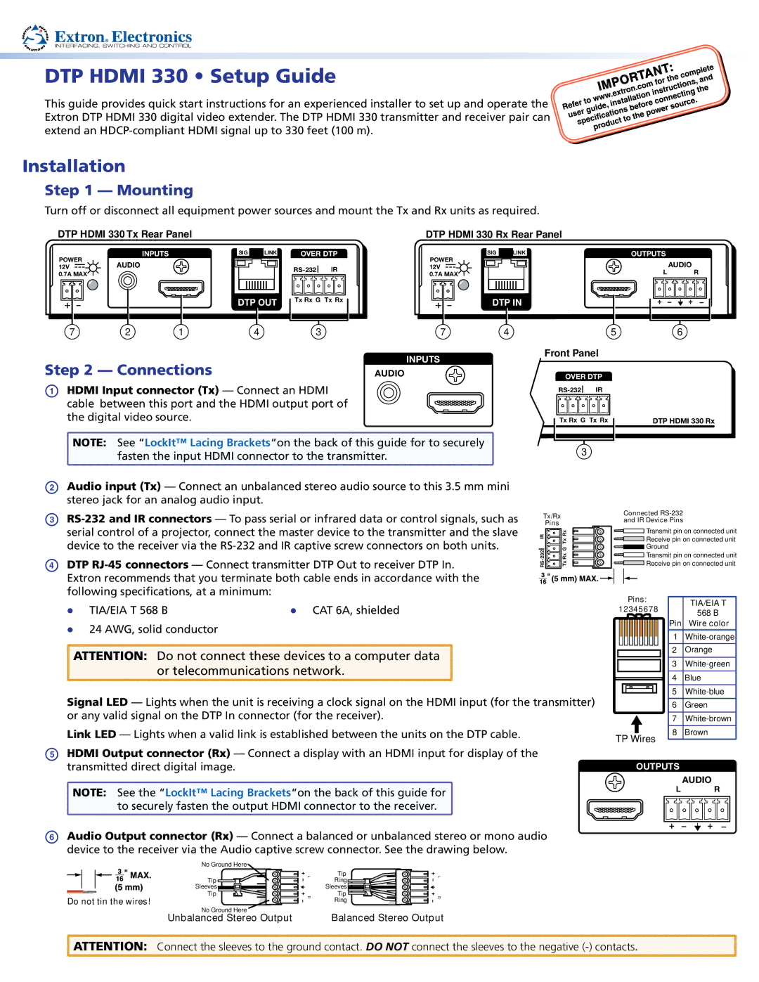
DTP HDMI 330 Tx Rear Panel
DTP HDMI 330 Rx Rear Panel
POWER
INPUTS
SIG ![]()
![]() LINK
LINK
OVER DTP
SIG | LINK | OUTPUTS |
POWER |
|
|
12VAUDIO
0.7A MAX
DTP OUT
IR | |
Tx Rx G Tx Rx | |
12V | L | AUDIO |
0.7A MAX | R |
DTP IN
7 | 2 | 1 | 4 | 3 | 7 | 4 | 5 | 6 |
|
|
|
|
| INPUTS |
| Front Panel |
|
Step 2 — Connections |
|
|
|
|
| |||
|
| AUDIO |
| OVER DTP |
| |||
A HDMI Input connector (Tx) — Connect an HDMI | IR | |
cable between this port and the HDMI output port of |
|
|
the digital video source. | Tx Rx G Tx Rx | |
NOTE: See “LockIt™ Lacing Brackets“on the back of this guide for to securely | 3 | |
fasten the input HDMI connector to the transmitter. | ||
|
DTP HDMI 330 Rx
BAudio input (Tx) — Connect an unbalanced stereo audio source to this 3.5 mm mini stereo jack for an analog audio input.
C
DDTP
Tx/Rx
Pins
IR | Tx Rx |
Rx G | |
RS | Tx |
Connected RS-232
and IR Device Pins
![]()
![]() Transmit pin on connected unit
Transmit pin on connected unit
![]()
![]() Receive pin on connected unit
Receive pin on connected unit
![]()
![]() Ground
Ground
![]()
![]() Transmit pin on connected unit
Transmit pin on connected unit ![]()
![]() Receive pin on connected unit
Receive pin on connected unit
zz | TIA/EIA T 568 B | z CAT 6A, shielded |
zz | 24 AWG, solid conductor |
|
ATTENTION: Do not connect these devices to a computer data or telecommunications network.
Pins:
12345678
TIA/EIA T
568 B
Pin Wire color
1 | |
|
|
2 | Orange |
|
|
3 | |
|
|
4 | Blue |
|
|
5 |
Signal LED — Lights when the unit is receiving a clock signal on the HDMI input (for the transmitter) or any valid signal on the DTP In connector (for the receiver).
Link LED — Lights when a valid link is established between the units on the DTP cable.
TP Wires
6 | Green |
|
|
7 | |
|
|
8 | Brown |
EHDMI Output connector (Rx) — Connect a display with an HDMI input for display of the transmitted direct digital image.
![]() NOTE: See the “LockIt™ Lacing Brackets“on the back of this guide for
NOTE: See the “LockIt™ Lacing Brackets“on the back of this guide for ![]()
![]() to securely fasten the output HDMI connector to the receiver.
to securely fasten the output HDMI connector to the receiver. ![]()
OUTPUTS
AUDIO
L R
FAudio Output connector (Rx) — Connect a balanced or unbalanced stereo or mono audio device to the receiver via the Audio captive screw connector. See the drawing below.
No Ground Here
Tip
Sleeves ![]()
![]()
![]()
![]()
![]()
![]()
![]()
Tip
Do not tin the wires!
L | Tip | L | |
| Ring |
| |
| Sleeves |
| |
R | Tip | R | |
Ring | |||
|
|
No Ground Here | Balanced Stereo Output |
Unbalanced Stereo Output |
![]() ATTENTION: Connect the sleeves to the ground contact. DO NOT connect the sleeves to the negative
ATTENTION: Connect the sleeves to the ground contact. DO NOT connect the sleeves to the negative