DVI DL 101 specifications
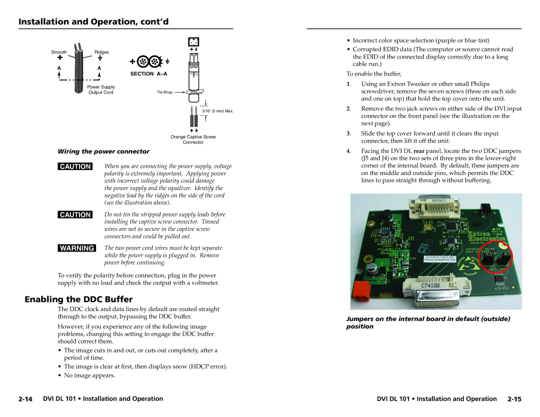
Extron Electronics DVI DL 101 is a state-of-the-art digital video distribution amplifier designed to provide superior performance in professional environments. This powerful device is particularly well-suited for applications requiring high-quality DVI signal distribution, making it an ideal choice for educational institutions, corporate settings, and broadcast studios.One of the standout features of the DVI DL 101 is its ability to distribute a single DVI-D signal to multiple displays without any loss of quality. With a single input and up to two DVI outputs, this device ensures that all connected displays receive the same high-quality image. The DVI DL 101 supports video resolutions up to 1920x1200 at a refreshing rate of 60 Hz, making it suitable for HD video applications.
The DVI DL 101 utilizes advanced signal processing technologies, including reclocking and equalization. Reclocking helps to regenerate the digital signal to eliminate any potential distortion that may occur over long cable runs. Meanwhile, equalization adjusts the signal strength to compensate for cable length and quality. Together, these technologies enhance the overall integrity of the digital signals, ensuring consistent and reliable performance across all outputs.
In terms of connectivity, the DVI DL 101 features a DVI-D input and two DVI-D outputs, accommodating various cable configurations. Additionally, the device is designed with a compact and durable chassis, making it easy to integrate into various rack-mounted setups or standalone configurations. The front panel includes LED indicators, providing users with real-time status updates on the power and signal presence.
Another characteristic of the DVI DL 101 is its ease of installation and user-friendly operation. With its plug-and-play functionality, users can quickly set up the device without the need for complex programming or configuration. Furthermore, the DVI DL 101 is compatible with a wide range of DVI sources, including computers, projectors, and digital signage systems.
Overall, the Extron DVI DL 101 is an exceptional choice for any professional environment needing reliable and high-quality DVI signal distribution. With its robust set of features, advanced signal processing technologies, and ease of installation, it stands out as a premier solution for enhancing digital video systems.

