Installation, cont’d
2.If the rear panel DVI connector opening is covered, remove the two screws that secure the cover to the back panel and remove the cover.
3. | Position the DVI card above J14 with the DVI connector facing |
| toward the rear of the switcher. Ensure the pins on the DVI |
| card properly align with the J14 socket to prevent bending. |
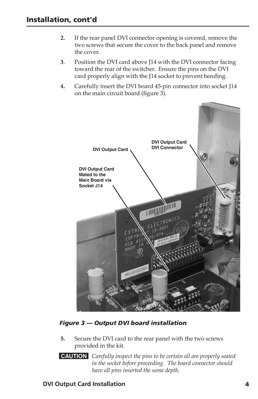
4.Carefully insert the DVI board
| DVI Output Card |
DVI Output Card | DVI Connector |
|
DVI Output Card
Mated to the
Main Board via
Socket J14
Figure 3 — Output DVI board installation
5.Secure the DVI card to the rear panel with the two screws provided in the kit.
CCarefully inspect the pins to be certain all are properly seated in the socket before proceeding. The board connector should have all pins inserted the same depth.
DVI Output Card Installation | 4 |