DVS 510 Series • Setup Guide (Continued)
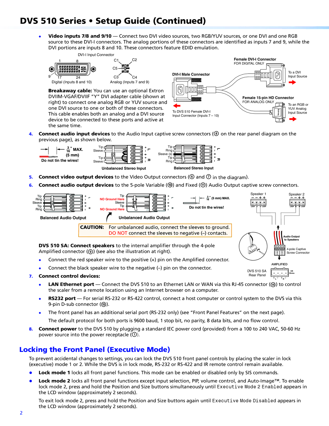
zz Video inputs 7/8 and 9/10 — Connect two DVI video sources, two RGB/YUV sources, or one DVI and one RGB source to these
|
|
| ||
| 1 | 8 | C1 | C2 |
|
|
| C5 |
|
9 | 17 | 24 | C3 | C4 |
| Digital (Inputs 8 and 10) | Analog (Inputs 7 and 9) | ||
Breakaway cable: You can use an optional Extron
This cable enables both an analog and a DVI source device to be connected to these ports and active at the same time.
To DVS 510 Female
Female
FOR DIGITAL ONLY
To a DVI
Input Source
Female
FOR ANALOG ONLY | To an RGB or |
| |
Extron | YUV Analog |
Input Source |
4.Connect audio input devices to the Audio Input captive screw connectors (H on the rear panel diagram on the previous page), as shown below.
Tip
Sleeve ![]()
![]()
![]()
![]()
![]()
Do not tin the wires! | Tip |
Sleeve |
L | Tip | |
Ring | ||
| ||
| Sleeve (s) | |
R | Tip | |
Ring | ||
|
![]() L R
L R
Unbalanced Stereo Input | Balanced Stereo Input |
5.Connect video output devices to the Video Output connectors (F and G in the diagram).
6.Connect audio output devices to the
Tip |
| Tip |
| Speaker 1 | |
L | L |
| |||
Ring | NO Ground Here |
| |||
|
|
| |||
Sleeve |
| Sleeve |
|
| |
Tip | R | Tip | R | Do not tin the wires! | |
Ring | NO Ground Here | ||||
|
|
|
Balanced Audio Output | Unbalanced Audio Output |
CAUTION: For unbalanced audio, connect the sleeves to ground.
DO NOT connect the sleeves to negative
DVS 510 SA: Connect speakers to the internal amplifier through the
zz Connect the red speaker wire to the positive (+) pin on the Amplified connector.
Speaker 2
Audio Output
to Speakers
Screw Connector
zz Connect the black speaker wire to the negative
7.Connect control devices:
DVS 510 SA Rear Panel
AMPLIFIED | |
| 4/8 |
| Ohms |
L | R |
zz LAN Ethernet port — Connect the DVS 510 to an Ethernet LAN or WAN via this
zz
zz
RS232 port — For serial
The front panel has an additional serial port
8.Connect power to the DVS 510 by plugging a standard IEC power cord (provided) from a 100 to 240 VAC,
Locking the Front Panel (Executive Mode)
To prevent accidental changes to settings, you can lock the DVS 510 front panel controls by placing the scaler in lock (executive) mode 1 or 2. While the DVS is in lock mode,
zz Lock mode 1 locks all front panel functions. This mode can be enabled or disabled only by SIS commands.
zz Lock mode 2 locks all front panel functions except input selection, PIP, volume control, and
To exit lock mode 2, press and hold the Position and Size buttons again until Executive Mode Disabled appears in the LCD window (approximately 2 seconds).
2