DVS 510 Series • Setup Guide
The Extron DVS 510 Series scalers are
![]() NOTE: For full installation, configuration, and operation details, see the DVS 510 Series User Guide, available at
NOTE: For full installation, configuration, and operation details, see the DVS 510 Series User Guide, available at
www.extron.com.
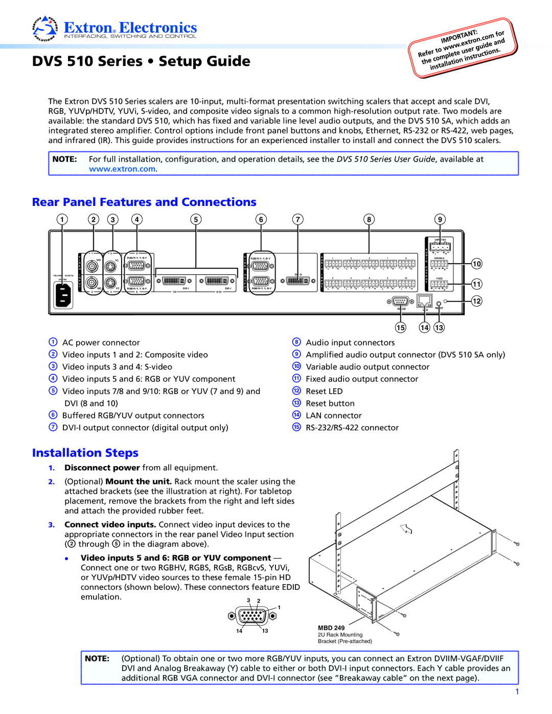
Rear Panel Features and Connections
1 |
| 2 |
|
| 1 |
| V |
|
| I | VID |
| D |
|
| E |
|
| O |
|
I |
| |
2A MAX | N |
|
P |
| |
|
| |
| U |
|
| T | VID |
|
|
2
3 | 4 | 5 |
|
| 6 | 7 |
|
|
|
|
|
| 8 |
|
|
|
|
| 9 |
|
|
|
|
|
|
|
|
|
|
|
|
|
|
|
|
|
|
|
| AMPLIFIED | |
|
|
|
|
|
|
|
|
|
|
|
|
|
|
|
|
|
| A |
|
|
3 | 5 |
|
|
|
|
|
|
|
|
|
|
|
|
|
|
|
| U | L | R |
|
|
|
|
|
|
|
|
|
|
|
|
|
|
|
| D | ||||
|
|
| V |
|
| A |
|
|
|
|
|
|
|
|
|
|
|
| ||
|
|
|
|
| 1 |
| 3 |
| 5 |
| 7 | 9 |
| I | VARIABLE | |||||
YC |
|
| I |
| U |
|
|
|
|
| ||||||||||
|
|
|
|
|
|
|
|
|
|
|
|
|
|
| O |
|
| |||
|
|
|
| D |
|
| D |
|
|
|
|
|
|
|
|
|
|
|
|
|
|
|
|
| E |
|
| I |
|
|
|
|
|
|
|
|
|
| O |
|
|
|
|
|
| O |
|
| O L | R | L | R | L | R | L | R | L | R | L | R | ||
|
|
|
|
|
| U | ||||||||||||||
|
|
|
|
|
|
|
|
|
|
|
|
|
|
|
|
|
| |||
|
|
|
| O |
| I |
|
|
|
|
|
|
|
|
|
| T |
|
| |
|
|
|
|
|
|
|
|
|
|
|
|
|
|
| P |
|
| |||
|
|
|
| U |
|
| N |
| 2 |
| 4 |
| 6 |
| 8 | 10 |
| FIXED |
| |
|
|
|
|
|
|
|
|
|
|
| U |
| ||||||||
|
|
|
| T |
|
| P |
|
|
|
|
|
|
|
|
|
|
| ||
|
|
|
|
|
|
|
|
|
|
|
|
|
|
|
| T |
|
| ||
|
|
|
| P |
|
| U |
|
|
|
|
|
|
|
|
|
|
|
| |
|
|
|
|
|
|
|
|
|
|
|
|
|
|
|
|
|
|
| ||
YC | U |
| T | L | R | L | R | L | R | L | R | L | R |
|
|
| ||||
T |
|
|
| L | R | |||||||||||||||
4 | 6 | 7/8 | 9/10 |
|
|
|
|
|
|
|
|
|
|
|
|
|
|
|
|
|
|
|
|
|
|
|
|
|
|
|
|
|
|
|
|
| RS232 |
| LAN | RESET |
|
|
|
|
|
|
|
|
|
|
|
|
|
|
|
|
|
|
|
| ||
|
|
|
|
|
|
|
|
|
|
|
|
|
|
|
| 15 |
| 14 | 13 |
|
10
11
12
A AC power connector | H |
B Video inputs 1 and 2: Composite video | I |
C Video inputs 3 and 4: | J |
D Video inputs 5 and 6: RGB or YUV component | K |
E Video inputs 7/8 and 9/10: RGB or YUV (7 and 9) and | L |
DVI (8 and 10) | M |
F Buffered RGB/YUV output connectors | N |
G | O |
Audio input connectors
Amplified audio output connector (DVS 510 SA only) Variable audio output connector
Fixed audio output connector Reset LED
Reset button LAN connector
Installation Steps
1. Disconnect power from all equipment.
2. (Optional) Mount the unit. Rack mount the scaler using the attached brackets (see the illustration at right). For tabletop placement, remove the brackets from the right and left sides and attach the provided rubber feet.
3. Connect video inputs. Connect video input devices to the appropriate connectors in the rear panel Video Input section (B through E in the diagram above).
zz Video inputs 5 and 6: RGB or YUV component —
Connect one or two RGBHV, RGBS, RGsB, RGBcvS, YUVi, |
| ||
or YUVp/HDTV video sources to these female |
| ||
connectors (shown below). These connectors feature EDID |
| ||
emulation. | 3 | 2 |
|
|
| ||
|
| 1 |
|
| 14 | 13 | MBD 249 |
| 2U Rack Mounting | ||
|
|
| |
Bracket
![]() NOTE: (Optional) To obtain one or two more RGB/YUV inputs, you can connect an Extron
NOTE: (Optional) To obtain one or two more RGB/YUV inputs, you can connect an Extron
DVI and Analog Breakaway (Y) cable to either or both
1