Front Panel Features
1 | 2 | 3 |
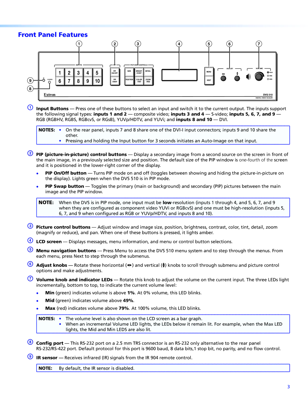
INPUTS | PIP | PICTURE CONTROLS |
|
|
| 1 | 2 | 3 | 4 | 5 | PIP | SIZE | BRIGHT | DETAIL |
|
|
|
|
|
|
|
| ON/OFF |
| /CONT |
|
9 | IR | CONFIG | 6 | 7 | 8 | 9 | 10 | PIP | POSITION | COLOR | ZOOM |
| |||||||||||
|
| SWAP |
| /TINT | /PAN |
8
4 | 5 | 6 | 7 |
ADJUST | VOLUME |
MENU | MAX |
| MID |
NEXT | MIN |
|
DVS 510
DIGITAL VIDEO SCALER
A Input Buttons — Press one of these buttons to select an input and switch it to the current output. The inputs support the following signal types: inputs 1 and 2 — composite video; inputs 3 and 4 —
![]() NOTES: • On the rear panel, inputs 7 and 8 share one of the
NOTES: • On the rear panel, inputs 7 and 8 share one of the
other.
• Pressing and holding the Input button for 3 seconds initiates an
B PIP
zz
zz
PIP On/Off button — Turns PIP mode on and off (toggles between showing and hiding the
PIP Swap button — Toggles the primary (main or background) and secondary (PIP) pictures between the main image and the PIP window.
![]() NOTE: When the DVS is in PIP mode, one input must be
NOTE: When the DVS is in PIP mode, one input must be
when they are configured as component video YUVi or RGBcvS) and one must be
C Picture control buttons — Adjust window and image size, position, brightness, contrast, color, tint, detail, zoom (magnify or reduce), and pan. When one of these buttons is pressed, it lights amber.
D
E Menu navigation buttons — Press Menu to access the DVS 510 menu system and to step through the menus. From each menu, press Next to step through the submenus.
F Adjust knobs — Rotate these horizontal ([) and vertical ({) knobs to scroll through submenu and picture control options and make adjustments.
G Volume knob and indicator LEDs — Rotate this knob to adjust the volume on the current input. The three LEDs light incrementally, bottom to top, to indicate the current volume level:
zz
zz
zz
Min (green) indicates volume is above 1%. At 0% volume, this LED blinks. Mid (green) indicates volume above 49%.
Max (red) indicates volume above 79%. At 100% volume, this LED blinks.
![]() NOTES: • The volume level is also shown on the LCD screen as a bar graph.
NOTES: • The volume level is also shown on the LCD screen as a bar graph.
• When an incremental Volume LED lights, the LEDs below it remain lit. For example, when the Max LED lights, the Mid and Min LEDS are also lit.
H Config port — This
I IR sensor
![]() NOTE: By default, the IR sensor is disabled.
NOTE: By default, the IR sensor is disabled.
3