MDA 3 Series specifications
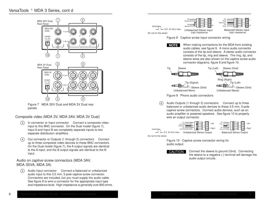
Extron Electronics is renowned for innovative solutions in the AV industry, and the MDA 3 Series is a testament to their commitment to high-quality performance and versatility. The MDA 3 Series is a family of multi-device adapters designed for professional audio and video applications, enabling seamless integration of various sources and displays in demanding environments.One of the standout features of the MDA 3 Series is its robust support for multiple video formats, including HDMI, HDBaseT, and other legacy signals, making it adaptable to various setups. The series is equipped with advanced signal processing technology that ensures optimal video quality, enhancing the overall viewing experience. This capability is particularly important in scenarios such as educational settings, boardrooms, and large venues, where clarity and precision are critical.
The MDA 3 Series also boasts extensive input options. Users can connect several devices, including laptops, cameras, and streaming devices, all through a single platform. The series supports resolutions up to 4K, ensuring compatibility with the latest high-definition content. This flexibility is enhanced by the inclusion of features like automatic input switching, which allows for a seamless transition between input sources, reducing downtime and maintaining audience engagement.
Moreover, the MDA 3 Series offers comprehensive control options. With Extron's control systems and third-party integration capabilities, users can easily manage multiple devices, adjust settings, and automate processes. This feature is particularly valuable in professional environments where quick response times and streamlined workflows are essential.
Efficiency and reliability are further enhanced by the MDA 3 Series' built-in scaling capabilities. The adapters can automatically adjust resolution and refresh rates, ensuring that content displays at its best on compatible screens. Additionally, the series incorporates Extron’s EDID management technology, which helps to eliminate common connectivity issues that can arise from mismatched device settings.
In terms of physical construction, the MDA 3 Series is designed for durability and ease of installation. It features a compact and rack-mountable design, allowing for straightforward integration into existing systems without taking up excessive space. This practicality is coupled with Extron's commitment to customer support and warranty programs, providing peace of mind for users investing in their solutions.
In summary, the Extron MDA 3 Series multi-device adapters are versatile, feature-rich solutions designed to enhance audiovisual performance in various professional settings. With their broad compatibility, advanced processing technologies, and user-friendly features, these units represent a significant advancement in the way AV environments are managed and optimized.

