Installation and Setup, cont’d
Measuring voltage for a TOA A-903MK2 amplifier
Control terminals for several TOA amplifiers are two screw terminals labeled “REMT VOL”. They do not indicate which terminal is for control voltage and which is for the ground. Use a voltmeter (set to VDC) to measure the voltage as shown here.
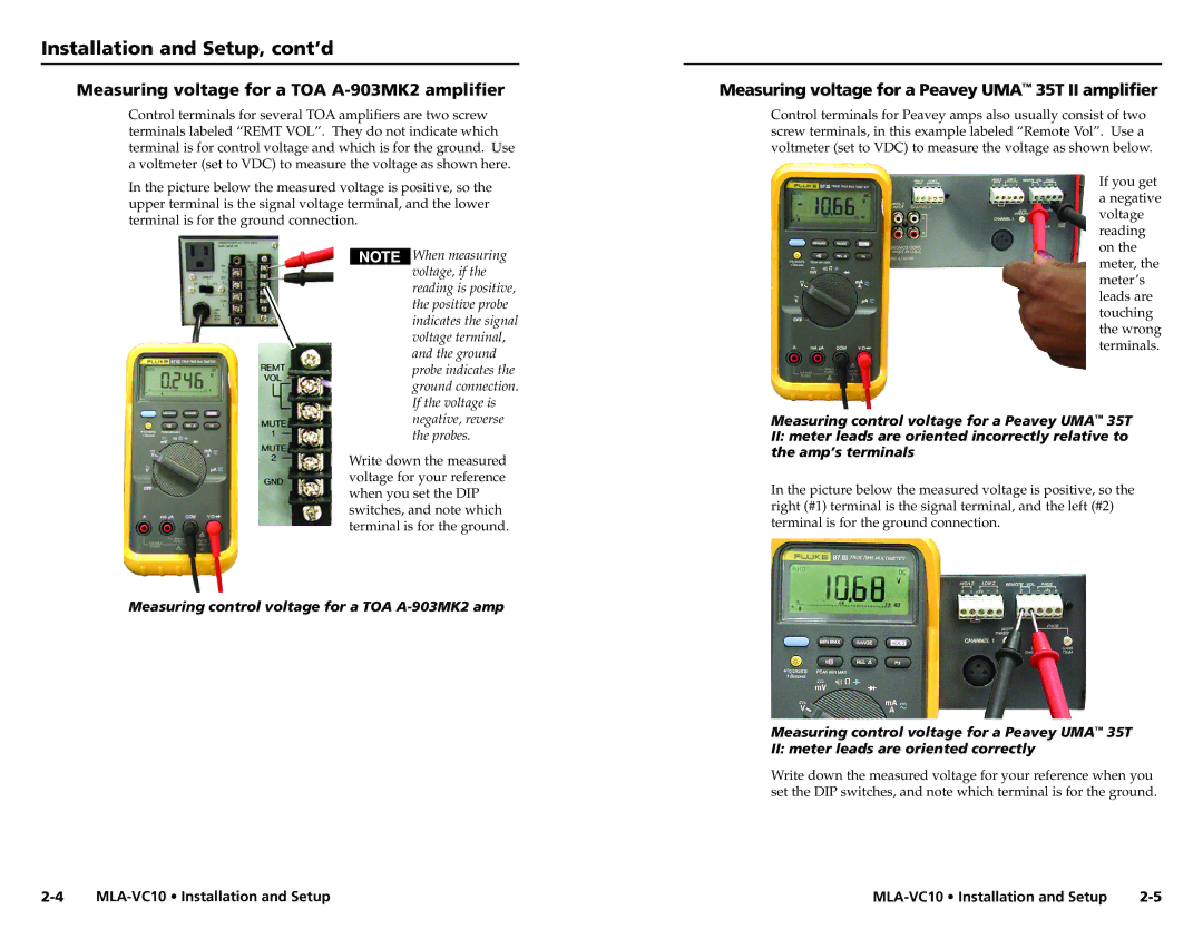
In the picture below the measured voltage is positive, so the upper terminal is the signal voltage terminal, and the lower terminal is for the ground connection.
![]()
![]()
![]()
![]()
![]() When measuring voltage, if the reading is positive, the positive probe indicates the signal voltage terminal, and the ground probe indicates the ground connection. If the voltage is negative, reverse the probes.
When measuring voltage, if the reading is positive, the positive probe indicates the signal voltage terminal, and the ground probe indicates the ground connection. If the voltage is negative, reverse the probes.
Write down the measured voltage for your reference when you set the DIP switches, and note which terminal is for the ground.
Measuring control voltage for a TOA
Measuring voltage for a Peavey UMA™ 35T II amplifier
Control terminals for Peavey amps also usually consist of two screw terminals, in this example labeled “Remote Vol”. Use a voltmeter (set to VDC) to measure the voltage as shown below.
If you get a negative voltage reading on the meter, the meter’s leads are touching the wrong terminals.
Measuring control voltage for a Peavey UMA™ 35T
II:meter leads are oriented incorrectly relative to the amp’s terminals
In the picture below the measured voltage is positive, so the right (#1) terminal is the signal terminal, and the left (#2) terminal is for the ground connection.
Measuring control voltage for a Peavey UMA™ 35T II: meter leads are oriented correctly
Write down the measured voltage for your reference when you set the DIP switches, and note which terminal is for the ground.