Installation and Setup, cont’d
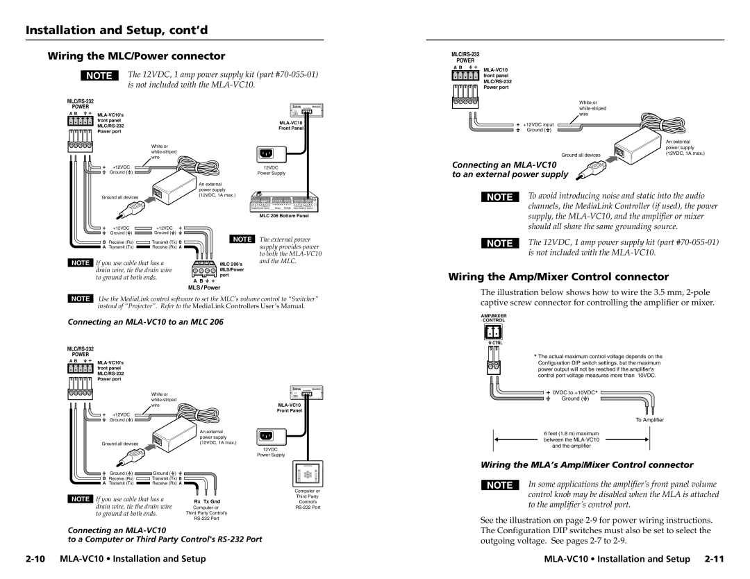
Wiring the MLC/Power connector
The 12VDC, 1 amp power supply kit (part
POWER
A B |
|
| |
| front panel |
| |
| Power port |
|
|
|
| |
POWER |
|
| MLC/POWER | |
|
|
|
| |
A B | POWER/ |
|
| |
STATUS | A | B | ||
| front panel |
|
| |
|
|
| ||
| Front Panel |
| ||
| Power port |
| ||
|
|
|
| |
+12VDC input Ground ( ![]() )
)
White or
White or |
| An external | |
| power supply | ||
Ground all devices | (12VDC, 1A max.) | ||
wire | |||
| |||
|
|
+12VDC | 12VDC |
Ground ( ) | Power Supply |
Connecting an
|
|
| An external |
|
|
|
|
|
| power supply |
|
|
|
Ground all devices |
| (12VDC, 1A max.) |
|
|
| |
|
|
|
|
| ||
|
|
| A B C D E A B C D E | 1A 1B 2A 2B 3A 3B A B C D | 1 2 3 4 5 6 A B | |
|
|
| IR |
| Tally Out MLS/Power | |
|
|
| Display/Source Control | Relays IR / RCM | Extron Switcher Control | |
|
|
|
| MLC 206 Bottom Panel | ||
+12VDC |
| +12VDC |
|
|
|
|
Ground ( | ) | Ground ( | ) |
|
|
|
To avoid introducing noise and static into the audio channels, the MediaLink Controller (if used), the power supply, the
B | Receive (Rx) | Transmit (Tx) B | NOTE |
A | Transmit (Tx) | Receive (Rx) A |
|
NOTE If you use cable that has a | MLC 206's | |
drain wire, tie the drain wire | MLS/Power | |
to ground at both ends. | port | |
A B | ||
|
The external power supply provides power to both the
The 12VDC, 1 amp power supply kit (part
Wiring the Amp/Mixer Control connector
MLS / Power
NOTE Use the MediaLink control software to set the MLC’s volume control to “Switcher” instead of “Projector”. Refer to the MediaLink Controllers User’s Manual.
Connecting an MLA-VC10 to an MLC 206
POWER
A B | |
| |
| front panel |
| |
| Power port |
|
| MLC/POWER |
White or | POWER/ |
|
STATUS | A B | |
|
| |
wire |
| |
| Front Panel |
|
+12VDC
Ground ( ![]() )
)
| An external |
| power supply |
Ground all devices | (12VDC, 1A max.) |
|
|
| 12VDC |
|
|
| Power Supply |
Ground ( ) | Ground ( | ) |
|
B Receive (Rx) | Transmit (Tx) B |
| |
A Transmit (Tx) | Receive (Rx) A |
| |
|
|
| Computer or |
NOTE If you use cable that has a | Rx Tx Gnd | Third Party | |
Control's | |||
drain wire, tie the drain wire | Computer or | ||
to ground at both ends. | Third Party Control's |
| |
|
|
| |
Connecting an
to a Computer or Third Party Control's
The illustration below shows how to wire the 3.5 mm,
AMP/MIXER
CONTROL
 CTRL
CTRL
*The actual maximum control voltage depends on the
Configuration DIP switch settings, but the maximum power output will not be reached if the amplifier's control port voltage measures more than 10VDC.
0VDC to +10VDC*
Ground (  )
)
To Amplifier
6 feet (1.8 m) maximum between the
Wiring the MLA’s Amp/Mixer Control connector
In some applications the amplifier’s front panel volume control knob may be disabled when the MLA is attached to the amplifier’s control port.
See the illustration on page