Installation and Setup, cont’d
Measuring voltage for a
Biamp Precedence CMA 60 amplifier
Several Biamp amplifiers have three screw terminals labeled “remote level”. The control voltage may be indicated (by a “C” in the following picture) on the
panel over the corresponding screw terminal, and the ground terminal is indicated with a .
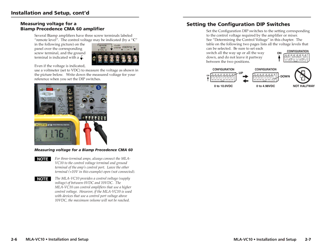
Even if the voltage is indicated,
use a voltmeter (set to VDC) to measure the voltage as shown in the picture below. Write down the measured voltage for your reference when you set the DIP switches.
Measuring voltage for a Biamp Precedence CMA 60
For
The
Setting the Configuration DIP Switches
Set the Configuration DIP switches to the setting corresponding to the control voltage required by the amplifier or mixer.
See “Determining the Control Voltage” in this chapter. The table on the following two pages lists all the voltage levels that can be selected. Be sure to set each
switch all the way up or all the way | ON |
| CONFIGURATION | ||||
1 | 2 | 3 | 4 5 6 7 8 | ||||
down, and do not leave it partway |
|
|
|
|
| ||
between the two positions. |
|
|
|
|
|
| |
CONFIGURATION | UP | CONFIGURATION |
|
|
|
|
|
1 2 3 4 5 6 7 8 | 1 2 3 4 5 6 7 8 |
|
|
|
|
| |
ON |
|
| DOWN |
|
| ||
|
|
|
|
| |||
0 to 10.0VDC |
| 0 to 4.98VDC |
|
|
|
| NOT HALFWAY |