MTP 1500RL 15HD RS SEQ • Setup Guide (Continued)
Step 5 — Power | A | 12V |
| |
|
| POWER |
| |
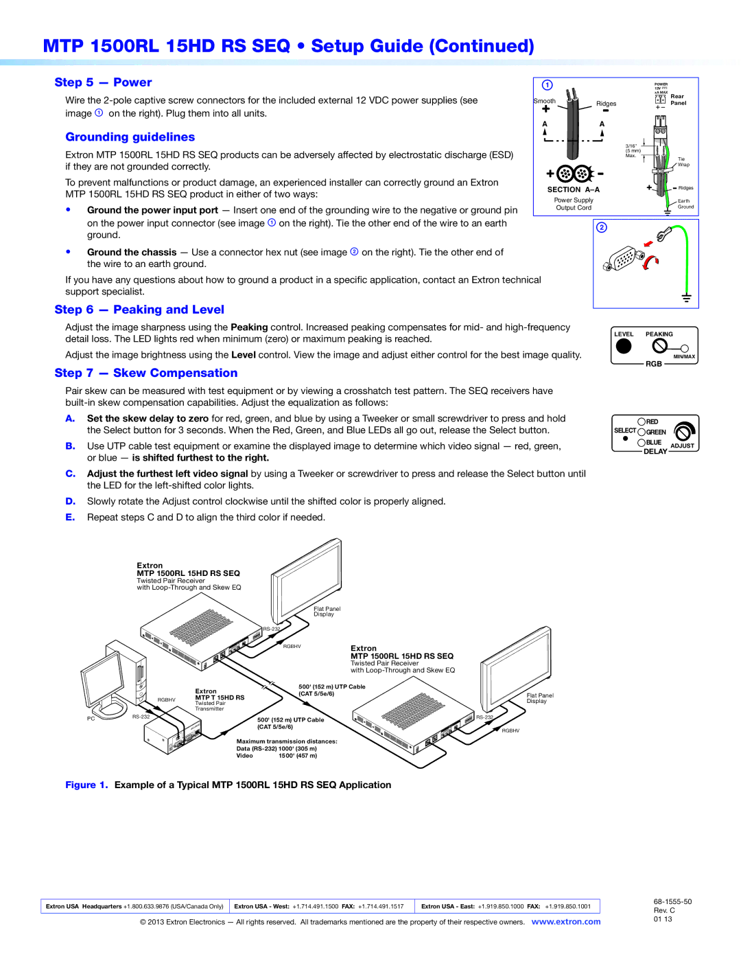
Wire the | Smooth | xA MAX | Rear | |
Ridges | Panel | |||
image A on the right). Plug them into all units. | A | A |
| |
|
| |||
Grounding guidelines |
| 3/16" |
| |
|
|
| ||
Extron MTP 1500RL 15HD RS SEQ products can be adversely affected by electrostatic discharge (ESD) |
| (5 mm) |
| |
| Max. | Tie | ||
if they are not grounded correctly. |
|
| ||
|
| Wrap | ||
To prevent malfunctions or product damage, an experienced installer can correctly ground an Extron | SECTION | Ridges | ||
MTP 1500RL 15HD RS SEQ product in either of two ways: | ||||
Power Supply |
| Earth | ||
• Ground the power input port — Insert one end of the grounding wire to the negative or ground pin |
| |||
Output Cord |
| Ground | ||
|
| |||
on the power input connector (see image A on the right). Tie the other end of the wire to an earth |
| B |
| |
ground. |
|
| ||
|
|
| ||
• Ground the chassis — Use a connector hex nut (see image B on the right). Tie the other end of the wire to an earth ground.
If you have any questions about how to ground a product in a specific application, contact an Extron technical support specialist.
Step 6 — Peaking and Level
Adjust the image sharpness using the Peaking control. Increased peaking compensates for mid- and
Adjust the image brightness using the Level control. View the image and adjust either control for the best image quality.
Step 7 — Skew Compensation
LEVEL PEAKING
MIN/MAX
RGB
Pair skew can be measured with test equipment or by viewing a crosshatch test pattern. The SEQ receivers have
A.Set the skew delay to zero for red, green, and blue by using a Tweeker or small screwdriver to press and hold the Select button for 3 seconds. When the Red, Green, and Blue LEDs all go out, release the Select button.
B.Use UTP cable test equipment or examine the displayed image to determine which video signal — red, green, or blue — is shifted furthest to the right.
C.Adjust the furthest left video signal by using a Tweeker or screwdriver to press and release the Select button until the LED for the
D.Slowly rotate the Adjust control clockwise until the shifted color is properly aligned.
E.Repeat steps C and D to align the third color if needed.
![]() RED
RED
SELECT ![]() GREEN
GREEN
BLUE ADJUST
DELAY
Extron
MTP 1500RL 15HD RS SEQ
Twisted Pair Receiver
with
| Extron | |
RGBHV | MTP T 15HD RS | |
Twisted Pair | ||
| ||
| Transmitter |
Flat Panel
Display
RGBHV | Extron |
| MTP 1500RL 15HD RS SEQ |
| Twisted Pair Receiver |
| with |
500' (152 m) UTP Cable (CAT 5/5e/6)
Flat Panel Display
PC | 500' (152 m) UTP Cable | |
| ||
|
| (CAT 5/5e/6) |
| Maximum transmission distances: | |
| Data | |
| Video | 1500' (457 m) |
RGBHV
Figure 1. Example of a Typical MTP 1500RL 15HD RS SEQ Application
|
|
|
|
|
Extron USA Headquarters +1.800.633.9876 (USA/Canada Only) | Extron USA - West: +1.714.491.1500 FAX: +1.714.491.1517 | Extron USA - East: +1.919.850.1000 FAX: +1.919.850.1001 |
| |
| Rev. C | |||
|
|
|
| |
© 2013 Extron Electronics — All rights reserved. All trademarks mentioned are the property of their respective owners. www.extron.com | 01 13 | |||