P/2 DA12 Series, P/2 DA8 specifications
Extron Electronics is a renowned company recognized for providing innovative and high-quality AV (audiovisual) solutions. Among their extensive range of products are the P/2 DA12 and P/2 DA8, which are designed to enhance video distribution in various environments. These distribution amplifiers are particularly favored in commercial settings like conference rooms, educational facilities, and control centers.The P/2 DA12 offers twelve outputs, while the P/2 DA8 features eight outputs, allowing for flexible video distribution from a single input source. Both models support resolutions up to 1920x1200, ensuring compatibility with a wide range of display devices such as projectors, monitors, and TVs. This high-quality video output is essential for maintaining the clarity and detail required in professional presentations and high-stakes environments.
One of the standout features of the P/2 DA series is Extron's advanced signal processing technology. This includes Automatic Cable Equalization, which compensates for signal loss over extended distances, ensuring that the video quality remains consistent even when using long cable runs. The P/2 DA amplifiers also integrate Extron's unique 4k-capable circuitry, making them ready for future-proofing as AV technology continues to evolve.
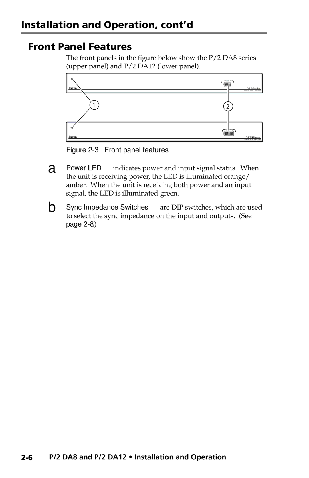
Furthermore, both models are equipped with individual gain controls for each output. This feature allows users to optimize the signal strength delivered to each display, accommodating different cable lengths and equipment configurations. The amplifiers also provide comprehensive status LED indicators that enable easy monitoring of device functionality and signal status, a crucial aspect in professional setups.
Reliability is another significant characteristic of the P/2 DA12 and P/2 DA8. These devices are built with robust construction, ensuring durability in demanding environments. They also feature universal power supplies that work globally, facilitating seamless integration into various installations without the need for additional converters.
Finally, installation is streamlined with the inclusion of a compact design, making it easy to mount in racks or on surfaces without occupying much space. The P/2 DA12 and P/2 DA8 are versatile solutions, enabling effective video distribution and enhancing the overall multimedia experience in any professional setting.

