Controls and Installation, cont’d
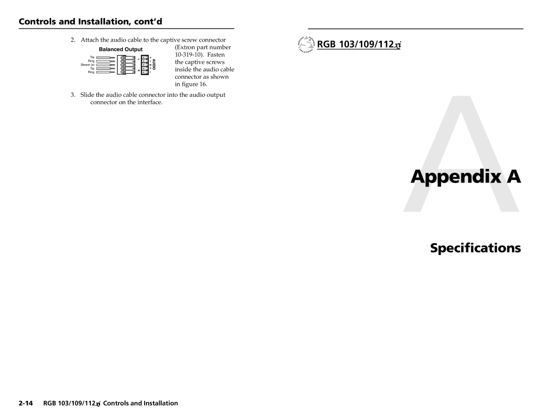
2. Attach the audio cable to the captive screw connector
Balanced Output | (Extron part number |
Tip | |
Sleeve (s) | the captive screws |
Ring | inside the audio cable |
Ring | |
Tip |
|
| connector as shown |
| in figure 16. |
3.Slide the audio cable connector into the audio output connector on the interface.