Controls and Installation, cont’d
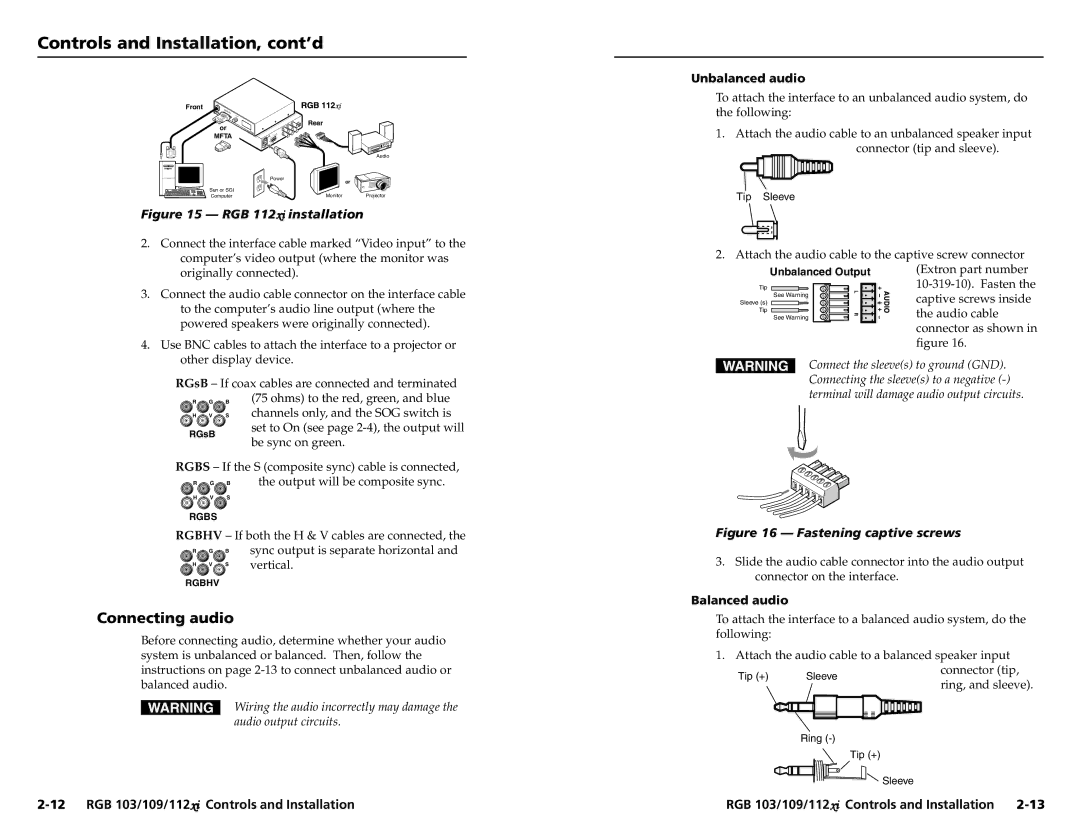
Front
Rear
or
Unbalanced audio
To attach the interface to an unbalanced audio system, do the following:
1. Attach the audio cable to an unbalanced speaker input |
MFTA
Power
Sun or SGI
Audio
or
connector (tip and sleeve). |
Computer | Monitor | Projector |
Figure 15 — RGB 112xi installation
2.Connect the interface cable marked “Video input” to the computer’s video output (where the monitor was originally connected).
3.Connect the audio cable connector on the interface cable to the computer’s audio line output (where the powered speakers were originally connected).
4.Use BNC cables to attach the interface to a projector or other display device.
RGsB – If coax cables are connected and terminated R G B (75 ohms) to the red, green, and blue ![]() H
H ![]() V
V ![]() S channels only, and the SOG switch is
S channels only, and the SOG switch is
Tip Sleeve
2. Attach the audio cable to the captive screw connector (Extron part number
captive screws inside the audio cable connector as shown in figure 16.
Connect the sleeve(s) to ground (GND). Connecting the sleeve(s) to a negative
RGsB
set to On (see page
RGBS – If the S (composite sync) cable is connected,
R | G | B | the output will be composite sync. |
H | V | S |
|
RGBS
RGBHV – If both the H & V cables are connected, the
R | G | B | sync output is separate horizontal and |
H | V | S | vertical. |
RGBHV
Connecting audio
Before connecting audio, determine whether your audio system is unbalanced or balanced. Then, follow the
Figure 16 — Fastening captive screws
3.Slide the audio cable connector into the audio output connector on the interface.
Balanced audio
To attach the interface to a balanced audio system, do the following:
1. Attach the audio cable to a balanced speaker input
instructions on page
Wiring the audio incorrectly may damage the audio output circuits.
Sleeve
Ring
connector (tip, ring, and sleeve).
Tip (+)
Sleeve
RGB 103/109/112xi Controls and Installation |