3.3.3.1 Switch Connections and HP Workstations
HP model xw workstations do not have console ports. Only the Root Administration Switch supports mixing nodes without console management ports with nodes that have console management ports (that is, all other supported server models).
HP workstations connected to the Root Administration Switch must be connected to the next
For example, if nodes with console management ports are connected to ports 42 through 36 on the Root Administration Switch, the console ports are connected to ports 42 through 36 on the Console Switch. Workstations must be connected starting at port 35 and lower to the Root Administration Switch; the corresponding ports on the Console Switch are empty.
3.3.4 Super Root Switch
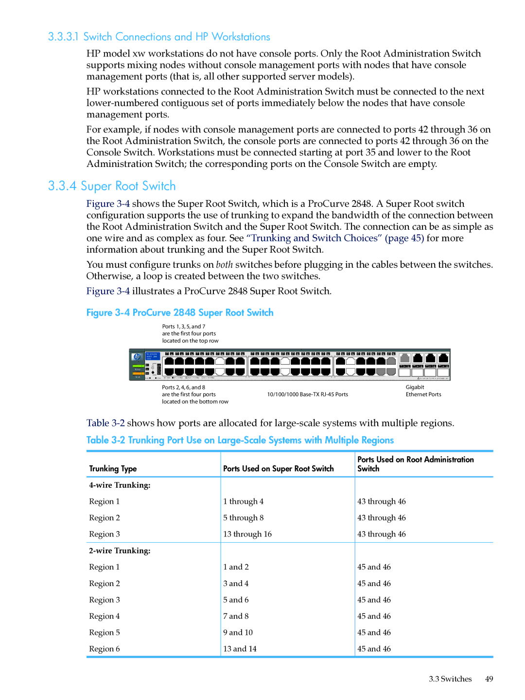
Figure 3-4 shows the Super Root Switch, which is a ProCurve 2848. A Super Root switch configuration supports the use of trunking to expand the bandwidth of the connection between the Root Administration Switch and the Super Root Switch. The connection can be as simple as one wire and as complex as four. See “Trunking and Switch Choices” (page 45) for more information about trunking and the Super Root Switch.
You must configure trunks on both switches before plugging in the cables between the switches. Otherwise, a loop is created between the two switches.
Figure 3-4 illustrates a ProCurve 2848 Super Root Switch.
Figure 3-4 ProCurve 2848 Super Root Switch
Ports 1, 3, 5, and 7 are the first four ports located on the top row
| hp procurve | 1 2 | 3 4 | 5 6 7 8 | 9 10 11 12 13 14 | 15 16 | 17 18 | 19 20 21 22 23 24 25 26 27 28 29 30 31 32 | 33 34 35 36 37 38 | 39 40 41 42 43 44 | |
| switch 2848 | 1 |
|
|
| 15 | 17 | 31 | 33 |
| |
| J4904A |
|
|
|
|
|
|
|
|
|
|
| RPS | LED | Lnk |
|
|
|
|
|
|
| T 45 M T 46 M T 47 M T 48 M |
|
| Ac t |
|
|
|
|
|
|
| ||
Po w er Fan | Mode |
|
|
|
|
|
|
|
| ||
| FD x |
|
|
|
|
|
|
|
| ||
|
|
|
|
|
|
|
|
|
|
| |
| Test |
| Sp d |
|
|
|
|
|
|
|
|
Fa ult | Re set |
| Cl ea r Spd m ode : | of f = 1 0 Mbps | fla sh = 10 0 Mbps | on = 10 0 0 Mbps | 16 | 18 | 32 | 34 | ! Us e onl y one (T or M) for ea ch G igabit port |
|
|
|
|
|
| ||||||
|
|
| Ports 2, 4, 6, and 8 |
|
|
|
| Gigabit | |||
|
|
| are the first four ports |
|
| 10/100/1000 | Ethernet Ports | ||||
|
|
| located on the bottom row |
|
|
|
|
| |||
Table
Table
|
| Ports Used on Root Administration |
Trunking Type | Ports Used on Super Root Switch | Switch |
|
|
|
Region 1 | 1 through 4 | 43 through 46 |
Region 2 | 5 through 8 | 43 through 46 |
Region 3 | 13 through 16 | 43 through 46 |
|
| |
Region 1 | 1 and 2 | 45 and 46 |
Region 2 | 3 and 4 | 45 and 46 |
Region 3 | 5 and 6 | 45 and 46 |
Region 4 | 7 and 8 | 45 and 46 |
Region 5 | 9 and 10 | 45 and 46 |
Region 6 | 13 and 14 | 45 and 46 |
3.3 Switches | 49 |