3.3.5 Root Administration Switch

The Root Administration Switch for the administration network of an HP XC system can be either a ProCurve 2848 switch or a ProCurve 2824 switch for small configurations.

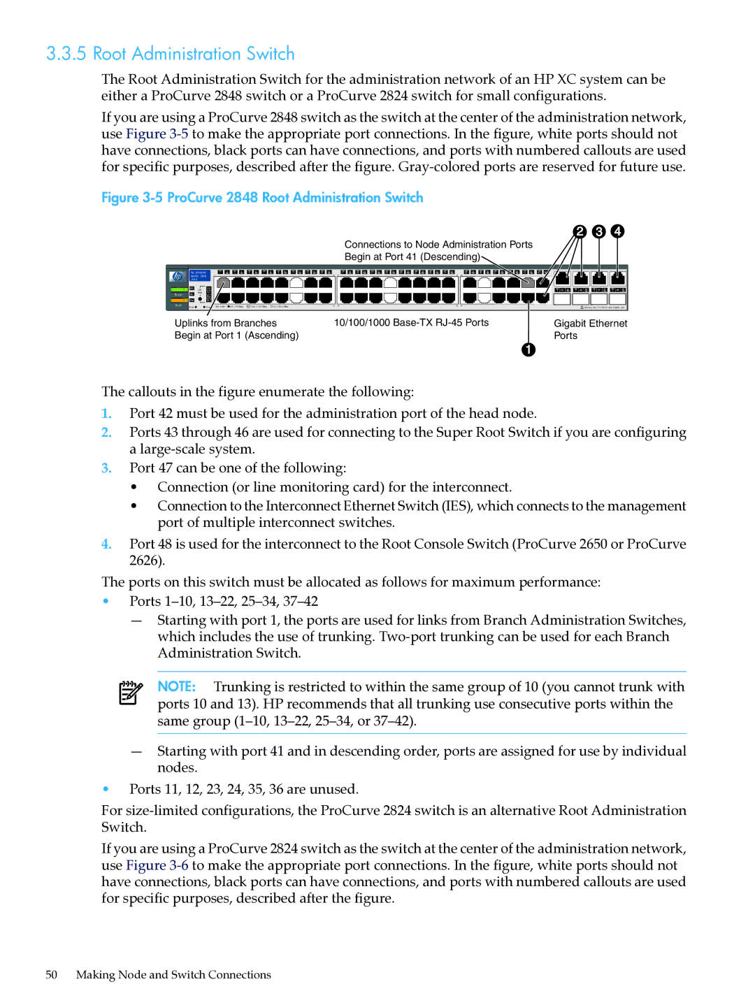
If you are using a ProCurve 2848 switch as the switch at the center of the administration network, use Figure 3-5to make the appropriate port connections. In the figure, white ports should not have connections, black ports can have connections, and ports with numbered callouts are used for specific purposes, described after the figure. Gray-colored ports are reserved for future use.

Figure 3-5 ProCurve 2848 Root Administration Switch


2

3

4


Connections to Node Administration Ports


Begin at Port 41 (Descending)


hp procurve


1

2

3

4

5

6

7

8

9

10

11

12

13

14

15

16


17

18

19

20

21

22

23

24

25

26

27

28

29

30

31

32


33

34

35

36

37

38

39

40

41

42

43

44


switch 2848


1


15

17

31

33


J4904A


RPS


Lnk


LED

Ac t


T

45

M

T

46

M

T

47

M

T

48

M


Po w er

Fan

Mode


FD x


Test


Sp d


Fa ult


Re set


Cl ea r Spd m ode :

of f = 10 Mbps


flash = 10 0 Mbps

on = 10 0 0 Mbps

16

18

32

34


!

Use onl y one (T or M) for ea ch Gigabit

port


Uplinks from Branches


10/100/1000 Base-TX RJ-45 Ports


Gigabit Ethernet


Begin at Port 1 (Ascending)


Ports


The callouts in the figure enumerate the following:

1.Port 42 must be used for the administration port of the head node.

2.Ports 43 through 46 are used for connecting to the Super Root Switch if you are configuring a large-scale system.

3.Port 47 can be one of the following:

Connection (or line monitoring card) for the interconnect.

Connection to the Interconnect Ethernet Switch (IES), which connects to the management port of multiple interconnect switches.

4.Port 48 is used for the interconnect to the Root Console Switch (ProCurve 2650 or ProCurve 2626).

The ports on this switch must be allocated as follows for maximum performance:

Ports 1–10, 13–22, 25–34, 37–42

Starting with port 1, the ports are used for links from Branch Administration Switches, which includes the use of trunking. Two-port trunking can be used for each Branch Administration Switch.

NOTE: Trunking is restricted to within the same group of 10 (you cannot trunk with ports 10 and 13). HP recommends that all trunking use consecutive ports within the same group (1–10,13–22,25–34, or 37–42).

Starting with port 41 and in descending order, ports are assigned for use by individual nodes.

Ports 11, 12, 23, 24, 35, 36 are unused.

For size-limited configurations, the ProCurve 2824 switch is an alternative Root Administration Switch.

If you are using a ProCurve 2824 switch as the switch at the center of the administration network, use Figure 3-6to make the appropriate port connections. In the figure, white ports should not have connections, black ports can have connections, and ports with numbered callouts are used for specific purposes, described after the figure.

50 Making Node and Switch Connections