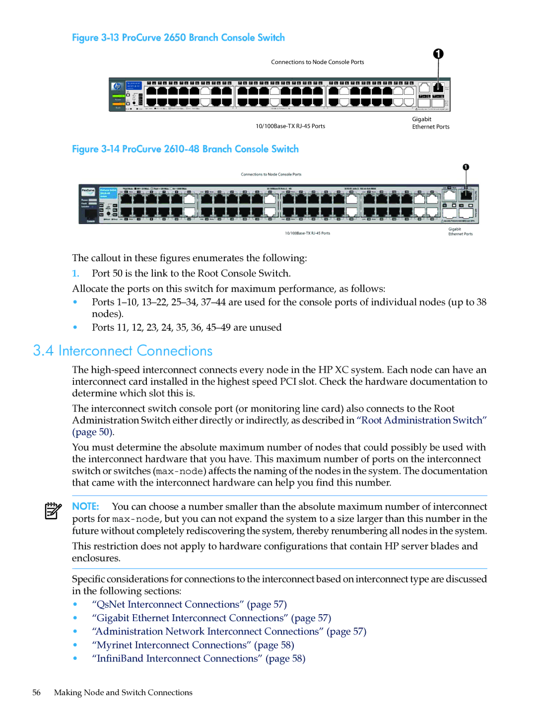
Figure 3-13 ProCurve 2650 Branch Console Switch
Connections to Node Console Ports
Po w er
Fa ult
| hp pr oc ur ve | 1 2 | 3 4 | 5 6 | 7 8 | 9 | 10 11 12 13 14 15 16 |
| 17 18 | 19 20 21 22 23 24 25 26 27 28 29 30 31 32 |
| 33 34 35 36 37 38 | 39 40 41 42 43 44 45 46 47 48 | |
| swi tch 26 5 0 | 1 |
|
|
|
|
| 15 | 17 |
| 31 | 33 | 47 | |
| J4 8 9 9 A |
|
|
|
|
|
|
|
|
|
|
|
| Gi g |
|
|
|
|
|
|
|
|
|
|
|
|
| Po rts | |
| Sel f |
|
|
|
|
|
|
|
|
|
|
|
|
|
| Te st |
|
|
|
|
|
|
|
|
|
|
|
|
|
| Po rt | Lnk |
|
|
|
|
|
|
|
|
|
|
| T 49 M T 50 M |
| LED | Ac t |
|
|
|
|
|
|
|
|
|
|
| |
| Vi ew |
|
|
|
|
|
|
|
|
|
|
|
| |
| Fa n | FD x |
|
|
|
|
|
|
|
|
|
|
| Mi ni- |
| Statu s |
|
|
|
|
|
|
|
|
|
|
| ||
|
| Sp d |
|
|
|
|
|
|
|
|
|
|
| GB IC |
|
|
|
|
|
|
|
|
|
|
|
|
|
| Po rts |
| Re set | Cl ea r | Spd m ode : | of f = 1 0 Mbp s, | fla sh = 10 0 | Mbps , | on = 10 0 0 | Mbps | 16 | 18 | 10/100Ba se | 32 | 34 | 48 |
|
|
|
|
| ! Us e onl y one (T or M) for ea ch G ig abit po rt | |||||||||
|
|
|
|
|
|
|
|
|
|
|
|
|
| Gigabit |
|
|
|
|
|
|
|
|
|
|
|
| Ethernet Ports | ||
Figure 3-14 ProCurve 2610-48 Branch Console Switch
The callout in these figures enumerates the following:
1.Port 50 is the link to the Root Console Switch.
Allocate the ports on this switch for maximum performance, as follows:
•Ports
•Ports 11, 12, 23, 24, 35, 36,
3.4Interconnect Connections
The
The interconnect switch console port (or monitoring line card) also connects to the Root Administration Switch either directly or indirectly, as described in “Root Administration Switch” (page 50).
You must determine the absolute maximum number of nodes that could possibly be used with the interconnect hardware that you have. This maximum number of ports on the interconnect switch or switches
NOTE: You can choose a number smaller than the absolute maximum number of interconnect ports for
This restriction does not apply to hardware configurations that contain HP server blades and enclosures.
Specific considerations for connections to the interconnect based on interconnect type are discussed in the following sections:
•“QsNet Interconnect Connections” (page 57)
•“Gigabit Ethernet Interconnect Connections” (page 57)
•“Administration Network Interconnect Connections” (page 57)
•“Myrinet Interconnect Connections” (page 58)
•“InfiniBand Interconnect Connections” (page 58)
56 Making Node and Switch Connections