2Power supply bays

3Insight Display. For more information, see “Insight Display” (page 28).

As shown in Figure 1-3, the HP BladeSystem c7000 enclosure can house a maximum of 16 half-height or 8 full-height server blades. The c7000 enclosure can contain a maximum of 6 power supplies and 10 fans. Figure 1-3also illustrates the numbering scheme for the server bays in which server blades are inserted. The numbering scheme differs for half height and full height server blades.

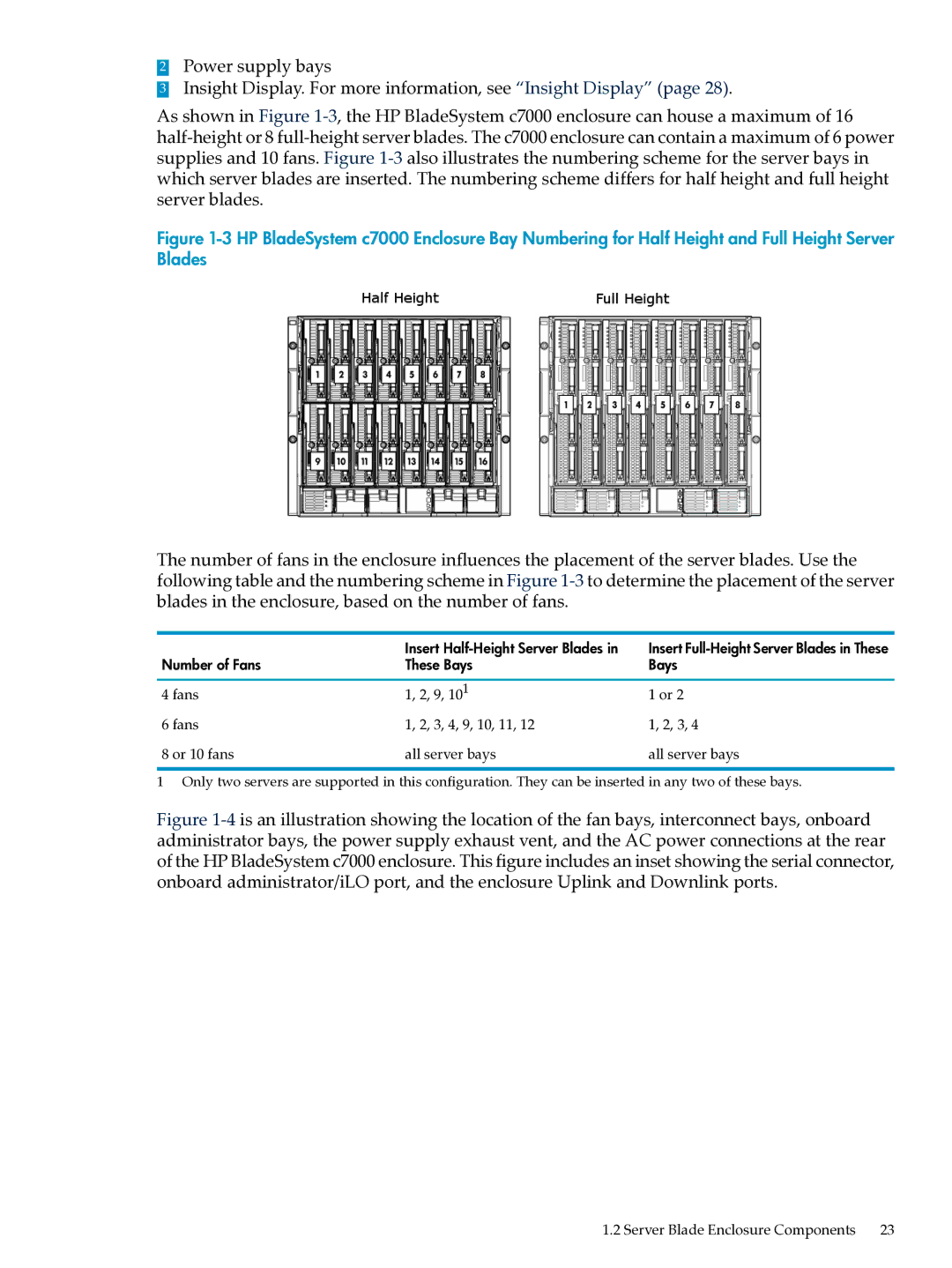
Figure 1-3 HP BladeSystem c7000 Enclosure Bay Numbering for Half Height and Full Height Server Blades

The number of fans in the enclosure influences the placement of the server blades. Use the following table and the numbering scheme in Figure 1-3to determine the placement of the server blades in the enclosure, based on the number of fans.


Insert Half-Height Server Blades in

Insert Full-Height Server Blades in These

Number of Fans

These Bays

Bays


4 fans

1, 2, 9, 101

1 or 2

6 fans

1, 2, 3, 4, 9, 10, 11, 12

1, 2, 3, 4

8 or 10 fans

all server bays

all server bays


1Only two servers are supported in this configuration. They can be inserted in any two of these bays.

Figure 1-4is an illustration showing the location of the fan bays, interconnect bays, onboard administrator bays, the power supply exhaust vent, and the AC power connections at the rear of the HP BladeSystem c7000 enclosure. This figure includes an inset showing the serial connector, onboard administrator/iLO port, and the enclosure Uplink and Downlink ports.

1.2 Server Blade Enclosure Components 23