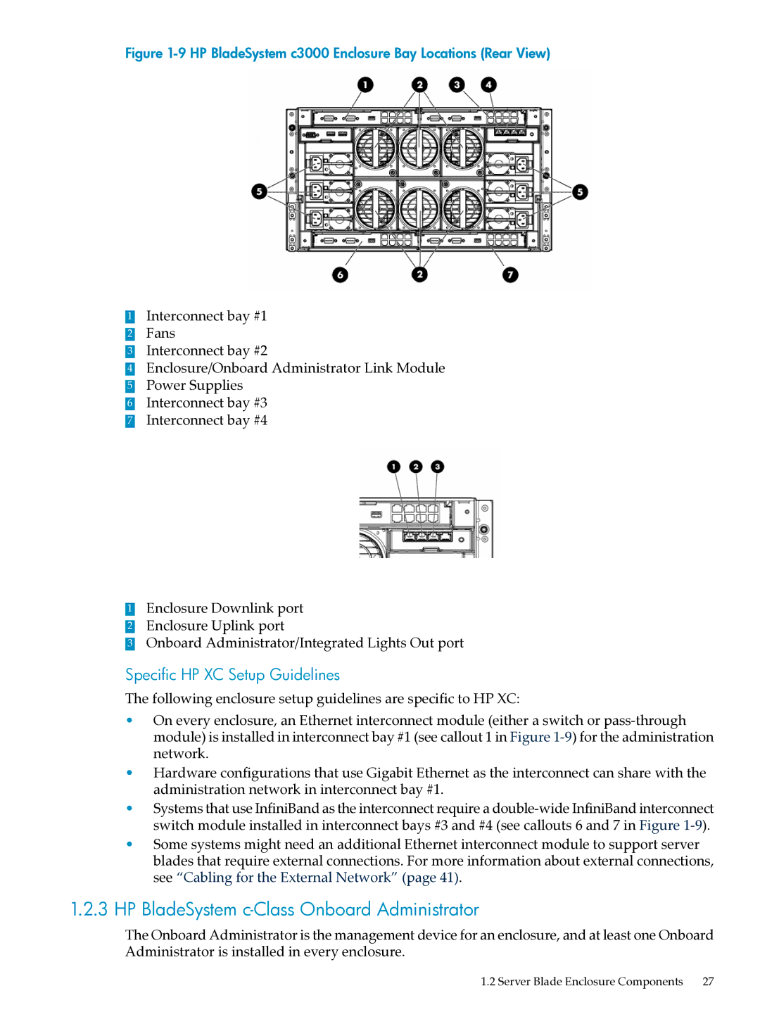
Figure 1-9 HP BladeSystem c3000 Enclosure Bay Locations (Rear View)
1Interconnect bay #1
2 Fans
3 Interconnect bay #2
4 Enclosure/Onboard Administrator Link Module
5 Power Supplies
6 Interconnect bay #3
7 Interconnect bay #4
1Enclosure Downlink port
2 Enclosure Uplink port
3 Onboard Administrator/Integrated Lights Out port
Specific HP XC Setup Guidelines
The following enclosure setup guidelines are specific to HP XC:
•On every enclosure, an Ethernet interconnect module (either a switch or
•Hardware configurations that use Gigabit Ethernet as the interconnect can share with the administration network in interconnect bay #1.
•Systems that use InfiniBand as the interconnect require a
•Some systems might need an additional Ethernet interconnect module to support server blades that require external connections. For more information about external connections, see “Cabling for the External Network” (page 41).
1.2.3HP BladeSystem c-Class Onboard Administrator
The Onboard Administrator is the management device for an enclosure, and at least one Onboard Administrator is installed in every enclosure.