4.7 Preparing the Hardware for CP4000 (AMD Opteron) Systems
Follow the procedures in this section to prepare each node before installing and configuring the HP XC System Software. See the following sections depending on the hardware model:
•“Preparing HP ProLiant DL145 Nodes” (page 87)
•“Preparing HP ProLiant DL145 G2 and DL145 G3 Nodes” (page 89)
•“Preparing HP ProLiant DL165 G5 Nodes” (page 93)
•“Preparing HP ProLiant DL365 Nodes” (page 94)
•“Preparing HP ProLiant DL365 G5 Nodes” (page 97)
•“Preparing HP ProLiant DL385 and DL385 G2 Nodes” (page 100)
•“Preparing HP ProLiant DL385 G5 Nodes” (page 104)
•“Preparing HP ProLiant DL585 and DL585 G2 Nodes” (page 106)
•“Preparing HP ProLiant DL585 G5 Nodes” (page 110)
•“Preparing HP ProLiant DL785 G5 Nodes” (page 113)
•“Preparing HP xw9300 and xw9400 Workstations” (page 116)
4.7.1Preparing HP ProLiant DL145 Nodes
On an HP ProLiant DL145 server, use the following tools to configure the appropriate settings for an HP XC system:
•BIOS Setup Utility
•Intelligent Platform Management Interface (IPMI) Utility
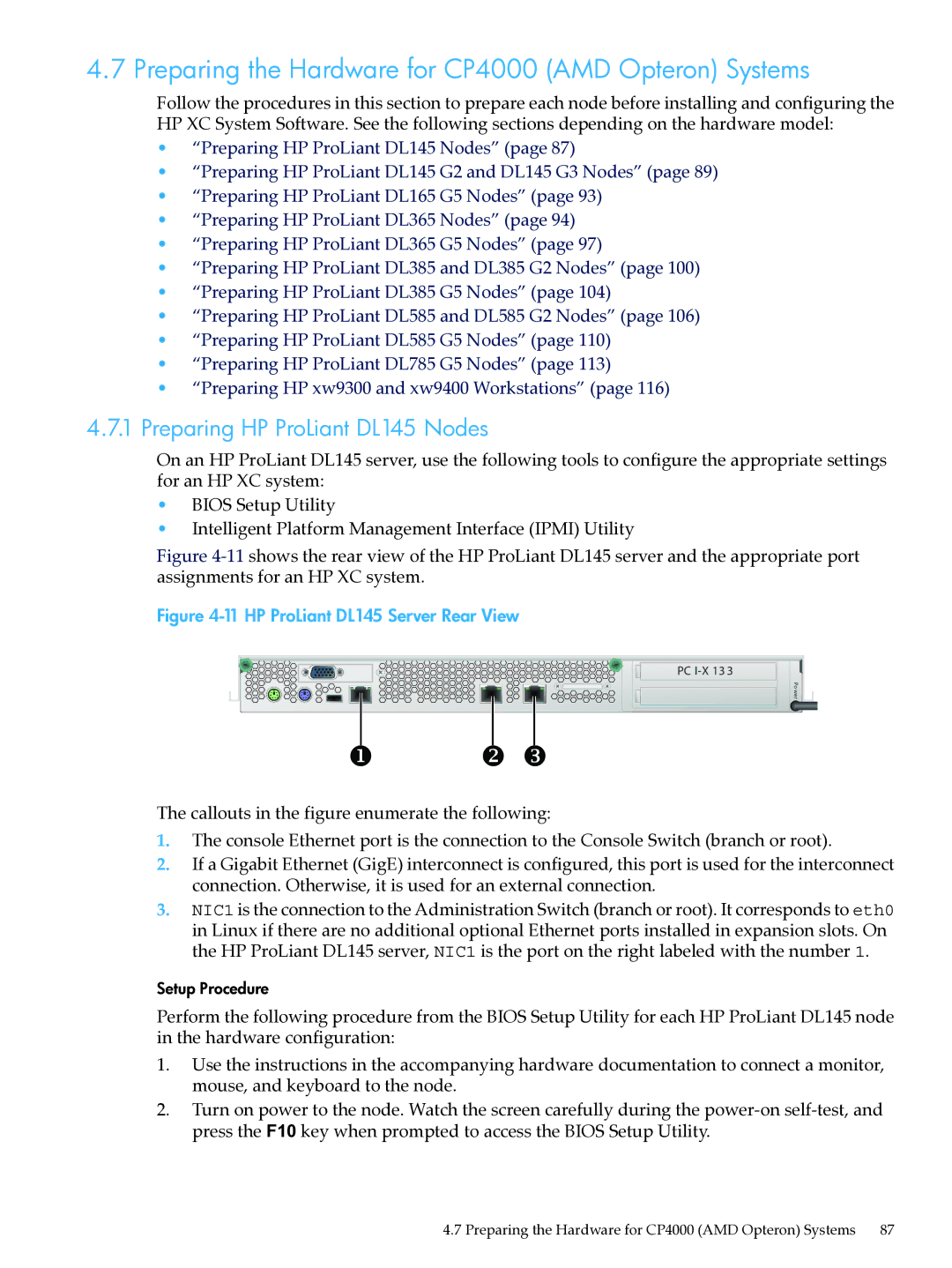
Figure 4-11 shows the rear view of the HP ProLiant DL145 server and the appropriate port assignments for an HP XC system.
Figure 4-11 HP ProLiant DL145 Server Rear View
PC
Po wer
The callouts in the figure enumerate the following:
1.The console Ethernet port is the connection to the Console Switch (branch or root).
2.If a Gigabit Ethernet (GigE) interconnect is configured, this port is used for the interconnect connection. Otherwise, it is used for an external connection.
3.NIC1 is the connection to the Administration Switch (branch or root). It corresponds to eth0 in Linux if there are no additional optional Ethernet ports installed in expansion slots. On the HP ProLiant DL145 server, NIC1 is the port on the right labeled with the number 1.
Setup Procedure
Perform the following procedure from the BIOS Setup Utility for each HP ProLiant DL145 node in the hardware configuration:
1.Use the instructions in the accompanying hardware documentation to connect a monitor, mouse, and keyboard to the node.
2.Turn on power to the node. Watch the screen carefully during the
4.7 Preparing the Hardware for CP4000 (AMD Opteron) Systems 87