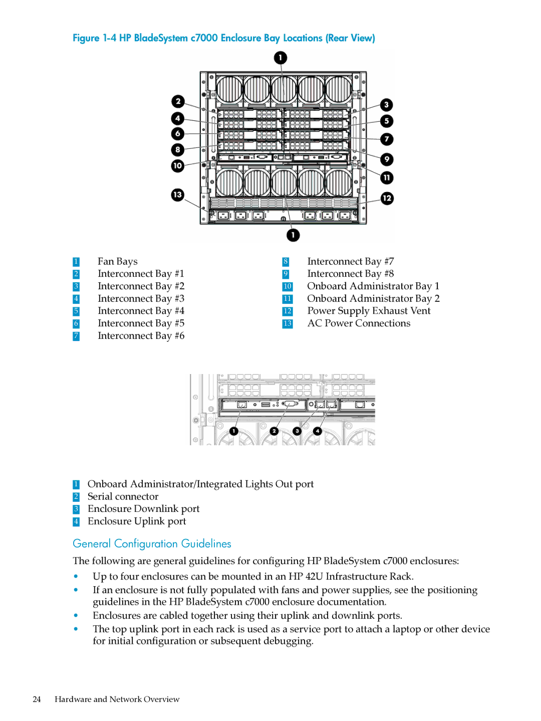
Figure 1-4 HP BladeSystem c7000 Enclosure Bay Locations (Rear View)
1 | Fan Bays | 8 | Interconnect Bay #7 |
2 | Interconnect Bay #1 | 9 | Interconnect Bay #8 |
3 | Interconnect Bay #2 | 10 | Onboard Administrator Bay 1 |
4 | Interconnect Bay #3 | 11 | Onboard Administrator Bay 2 |
5 | Interconnect Bay #4 | 12 | Power Supply Exhaust Vent |
6 | Interconnect Bay #5 | 13 | AC Power Connections |
7Interconnect Bay #6
1Onboard Administrator/Integrated Lights Out port
2 Serial connector
3 Enclosure Downlink port
4 Enclosure Uplink port
General Configuration Guidelines
The following are general guidelines for configuring HP BladeSystem c7000 enclosures:
•Up to four enclosures can be mounted in an HP 42U Infrastructure Rack.
•If an enclosure is not fully populated with fans and power supplies, see the positioning guidelines in the HP BladeSystem c7000 enclosure documentation.
•Enclosures are cabled together using their uplink and downlink ports.
•The top uplink port in each rack is used as a service port to attach a laptop or other device for initial configuration or subsequent debugging.
24 Hardware and Network Overview