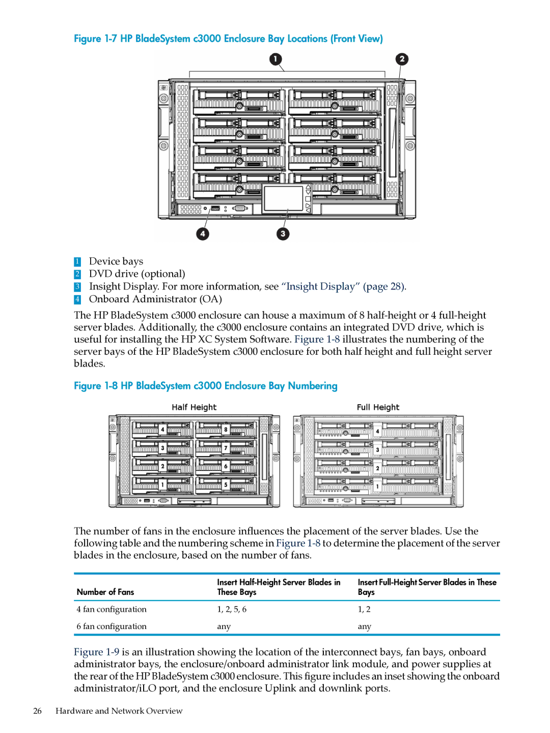
Figure 1-7 HP BladeSystem c3000 Enclosure Bay Locations (Front View)
1Device bays
2DVD drive (optional)
3Insight Display. For more information, see “Insight Display” (page 28).
4 Onboard Administrator (OA)
The HP BladeSystem c3000 enclosure can house a maximum of 8
Figure 1-8 HP BladeSystem c3000 Enclosure Bay Numbering
The number of fans in the enclosure influences the placement of the server blades. Use the following table and the numbering scheme in Figure
| Insert | Insert |
Number of Fans | These Bays | Bays |
4 fan configuration | 1, 2, 5, 6 | 1, 2 |
6 fan configuration | any | any |
Figure 1-9 is an illustration showing the location of the interconnect bays, fan bays, onboard administrator bays, the enclosure/onboard administrator link module, and power supplies at the rear of the HP BladeSystem c3000 enclosure. This figure includes an inset showing the onboard administrator/iLO port, and the enclosure Uplink and downlink ports.
26 Hardware and Network Overview
