—Starting with port 1, the ports are used for links from Branch Console Switches. Trunking is not used.
—Starting with port 21 and in descending order, ports are assigned for use by individual nodes in the utility cabinet. Nodes in the utility cabinet are connected directly to the Root Administration Switch.
NOTE: There must be at least one idle port in this set to indicate the dividing line between branch links and root node administration ports.
•Ports 11, 12, 23, and 24, are unused.
3.3.6.4ProCurve 2610-24 Switch
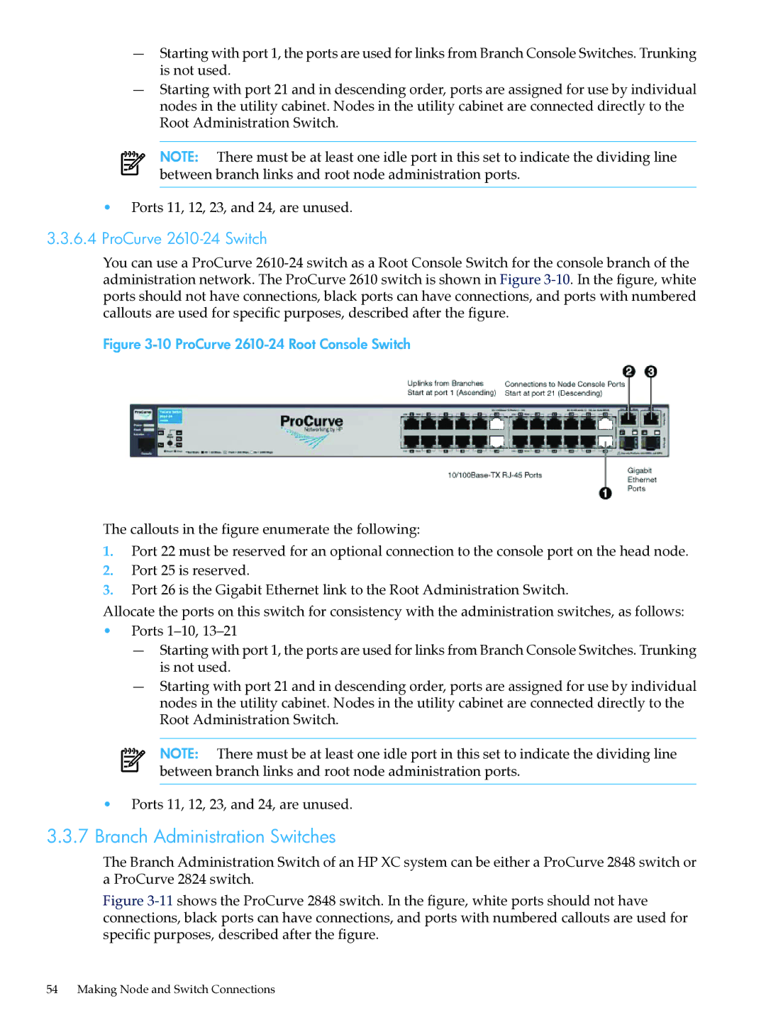
You can use a ProCurve
Figure 3-10 ProCurve 2610-24 Root Console Switch
The callouts in the figure enumerate the following:
1.Port 22 must be reserved for an optional connection to the console port on the head node.
2.Port 25 is reserved.
3.Port 26 is the Gigabit Ethernet link to the Root Administration Switch.
Allocate the ports on this switch for consistency with the administration switches, as follows:
•Ports
—Starting with port 1, the ports are used for links from Branch Console Switches. Trunking is not used.
—Starting with port 21 and in descending order, ports are assigned for use by individual nodes in the utility cabinet. Nodes in the utility cabinet are connected directly to the Root Administration Switch.
NOTE: There must be at least one idle port in this set to indicate the dividing line between branch links and root node administration ports.
•Ports 11, 12, 23, and 24, are unused.
3.3.7Branch Administration Switches
The Branch Administration Switch of an HP XC system can be either a ProCurve 2848 switch or a ProCurve 2824 switch.
Figure 3-11 shows the ProCurve 2848 switch. In the figure, white ports should not have connections, black ports can have connections, and ports with numbered callouts are used for specific purposes, described after the figure.
54 Making Node and Switch Connections