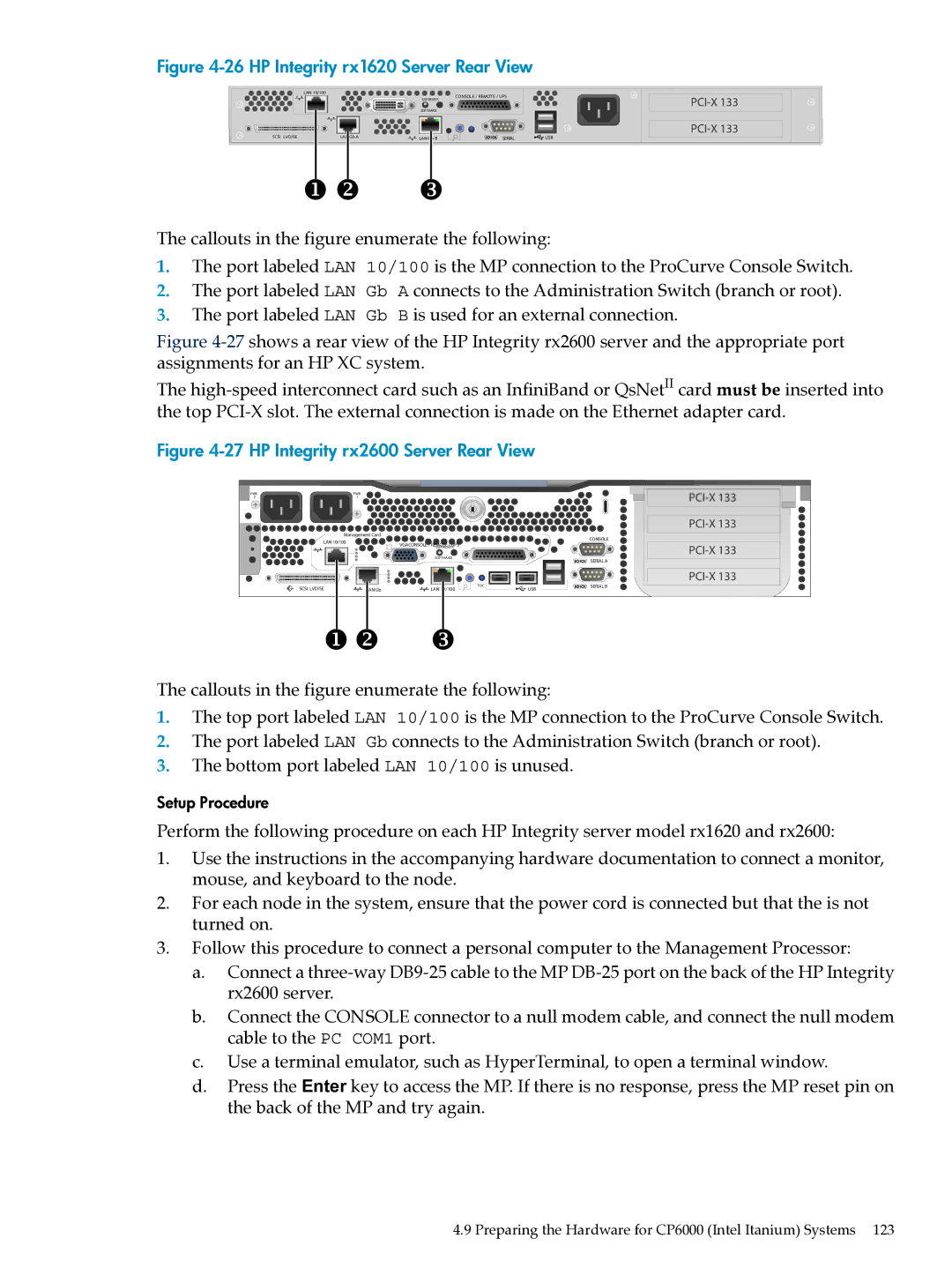
Figure 4-26 HP Integrity rx1620 Server Rear View
LAN 10/100
CONSOLE / REMOTE / UPS
GSP RESETS
SOFTHARD
SCSI LVD/SE | LAN Gb A |
|
| |
LAN Gb B | SERIAL | USB |
The callouts in the figure enumerate the following:
1.The port labeled LAN 10/100 is the MP connection to the ProCurve Console Switch.
2.The port labeled LAN Gb A connects to the Administration Switch (branch or root).
3.The port labeled LAN Gb B is used for an external connection.
Figure 4-27 shows a rear view of the HP Integrity rx2600 server and the appropriate port assignments for an HP XC system.
The high-speed interconnect card such as an InfiniBand or QsNetII card must be inserted into the top PCI-X slot. The external connection is made on the Ethernet adapter card.
Figure 4-27 HP Integrity rx2600 Server Rear View
PWR | PWR |
21
Management Card
LAN 10/100 | CONSOLE |
VGACONSOLE / REMOTE / UPS | |
| GSP RESETS |
SOFTHARD
SERIAL A
|
|
|
| |
SCSI LVD/SE | LAN Gb | TOC | USB | SERIAL B |
LAN 10/100 |
|
The callouts in the figure enumerate the following:
1.The top port labeled LAN 10/100 is the MP connection to the ProCurve Console Switch.
2.The port labeled LAN Gb connects to the Administration Switch (branch or root).
3.The bottom port labeled LAN 10/100 is unused.
Setup Procedure
Perform the following procedure on each HP Integrity server model rx1620 and rx2600:
1.Use the instructions in the accompanying hardware documentation to connect a monitor, mouse, and keyboard to the node.
2.For each node in the system, ensure that the power cord is connected but that the is not turned on.
3.Follow this procedure to connect a personal computer to the Management Processor:
a.Connect a
b.Connect the CONSOLE connector to a null modem cable, and connect the null modem cable to the PC COM1 port.
c.Use a terminal emulator, such as HyperTerminal, to open a terminal window.
d.Press the Enter key to access the MP. If there is no response, press the MP reset pin on the back of the MP and try again.
4.9 Preparing the Hardware for CP6000 (Intel Itanium) Systems 123