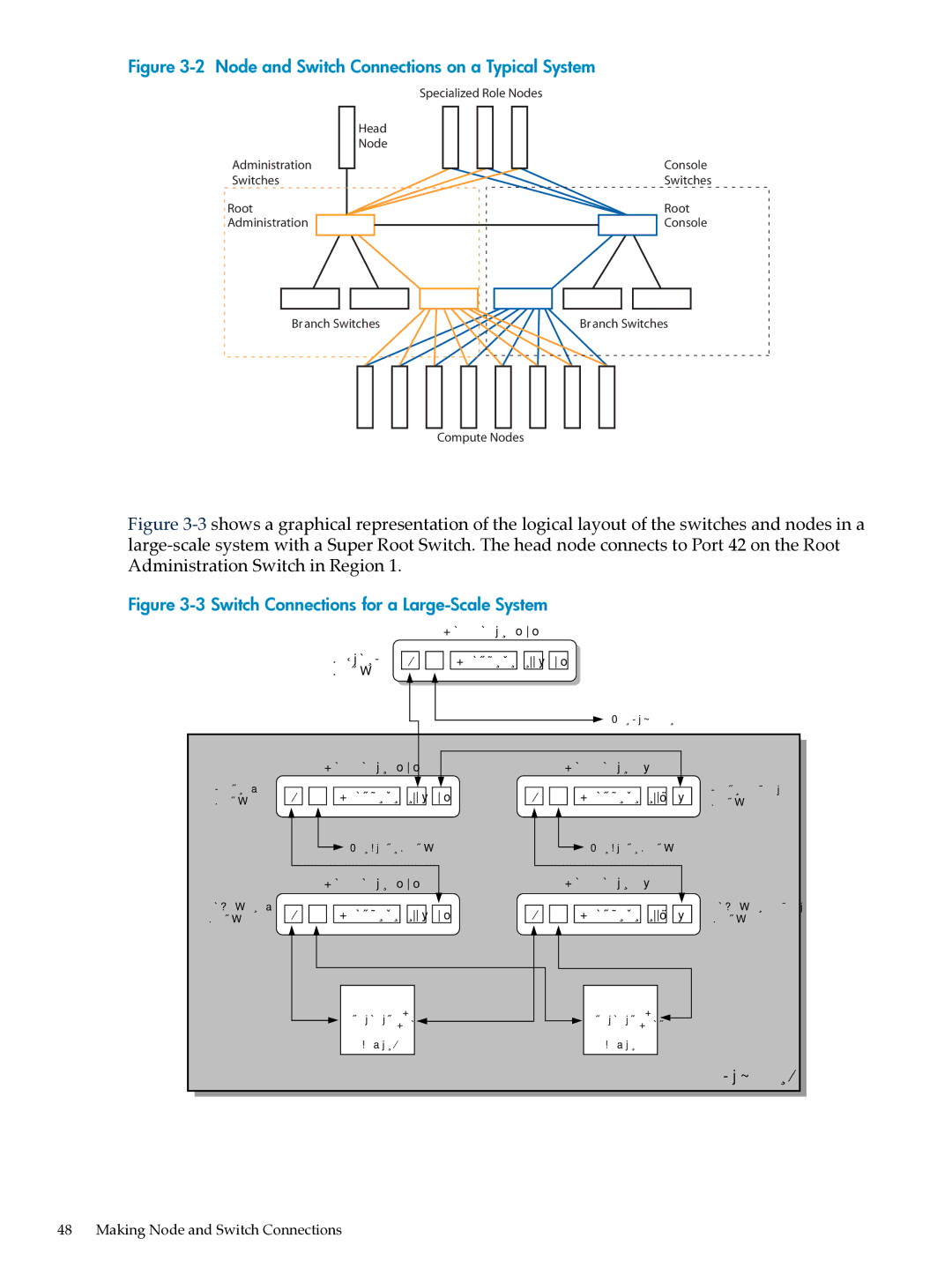
Figure 3-2 Node and Switch Connections on a Typical System
| Specialized Role Nodes |
| Head |
| Node |
Administration | Console |
Switches | Switches |
Root | Root |
Administration | Console |
Branch Switches
Branch Switches
Compute Nodes
Figure 3-3 shows a graphical representation of the logical layout of the switches and nodes in a large-scale system with a Super Root Switch. The head node connects to Port 42 on the Root Administration Switch in Region 1.
Figure 3-3 Switch Connections for a Large-Scale System
ProCurve 2848
Super Root 1 2 Ports 3 - 45 46 48
Switch
![]() To Region 2
To Region 2
|
| ProCurve 2848 |
|
|
| ProCurve 2650 |
|
|
| |||
Root Admin | 1 | 2 | Ports 3 - 45 | 46 | 48 | 1 | 2 | Ports 3 - 47 | 48 | 50 | Root Console | |
Switch | Switch | |||||||||||
|
|
|
|
|
|
|
|
|
| |||
|
|
| To Next Switch |
|
|
| To Next Switch |
|
| |||
|
| ProCurve 2848 |
|
|
| ProCurve 2650 |
|
|
| |||
Branch Admin | 1 | 2 | Ports 3 - 45 | 46 | 48 | 1 | 2 | Ports 3 - 47 | 48 | 50 | Branch Console | |
Switch | Switch | |||||||||||
Ethernet | CP | Ethernet | CP | |
Port | Port | |||
|
| |||
Node 1 | Node 2 | |||
Region 1
48 Making Node and Switch Connections