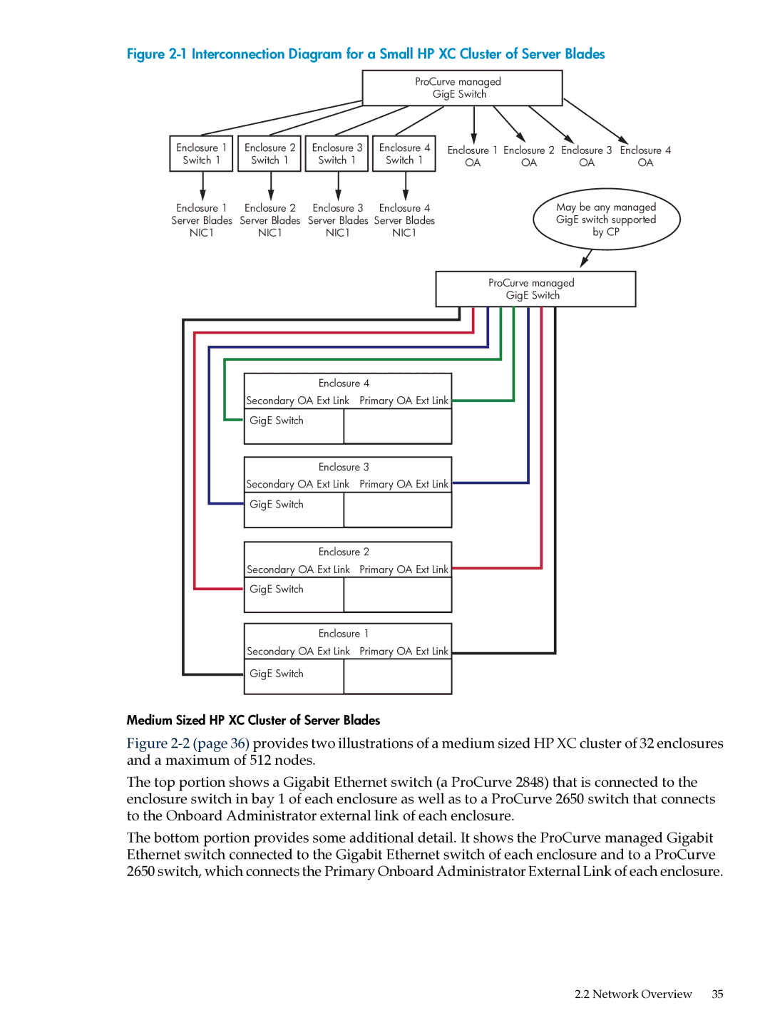
Figure 2-1 Interconnection Diagram for a Small HP XC Cluster of Server Blades
ProCurve managed
GigE Switch
|
|
|
|
|
|
|
|
|
|
|
|
|
|
|
|
Enclosure 1 |
| Enclosure 2 |
| Enclosure 3 |
| Enclosure 4 | Enclosure 1 Enclosure 2 | Enclosure 3 | Enclosure 4 | ||||||
Switch 1 |
| Switch 1 |
| Switch 1 |
| Switch 1 | OA | OA | OA | OA | |||||
|
|
|
|
|
|
|
|
|
|
|
|
|
|
|
|
|
|
|
|
|
|
|
|
|
|
|
|
|
|
|
|
Enclosure 1 | Enclosure 2 | Enclosure 3 | Enclosure 4 |
Server Blades | Server Blades | Server Blades | Server Blades |
NIC1 | NIC1 | NIC1 | NIC1 |
Enclosure 4
| Secondary OA Ext Link | Primary OA Ext Link | |
| GigE Switch |
|
|
|
|
| |
|
| ||
| Enclosure 3 | ||
| Secondary OA Ext Link | Primary OA Ext Link | |
| GigE Switch |
|
|
|
|
| |
|
|
| |
|
| ||
| Enclosure 2 | ||
| Secondary OA Ext Link | Primary OA Ext Link | |
| GigE Switch |
|
|
|
|
| |
|
| ||
| Enclosure 1 | ||
| Secondary OA Ext Link | Primary OA Ext Link | |
| GigE Switch |
|
|
|
|
|
|
May be any managed GigE switch supported by CP
ProCurve managed
GigE Switch
Medium Sized HP XC Cluster of Server Blades
Figure 2-2 (page 36) provides two illustrations of a medium sized HP XC cluster of 32 enclosures and a maximum of 512 nodes.
The top portion shows a Gigabit Ethernet switch (a ProCurve 2848) that is connected to the enclosure switch in bay 1 of each enclosure as well as to a ProCurve 2650 switch that connects to the Onboard Administrator external link of each enclosure.
The bottom portion provides some additional detail. It shows the ProCurve managed Gigabit Ethernet switch connected to the Gigabit Ethernet switch of each enclosure and to a ProCurve 2650 switch, which connects the Primary Onboard Administrator External Link of each enclosure.