4.Select Exit→Saving Changes to exit the BIOS Setup Utility.
5.Repeat this procedure for each HP ProLiant DL145 G2 and DL145 G3 node in the hardware configuration.
4.7.3Preparing HP ProLiant DL165 G5 Nodes
Use the BIOS Setup utility on HP ProLiant DL165 G5 servers to configure the appropriate settings for an HP XC system.
For this hardware model, you cannot set or modify the default console port password through the BIOS Setup Utility the way you can for other hardware models. The HP XC System Software Installation Guide documents the procedure to modify the console port password. You are instructed to perform the task just after the discover command discovers the IP addresses of the console ports.
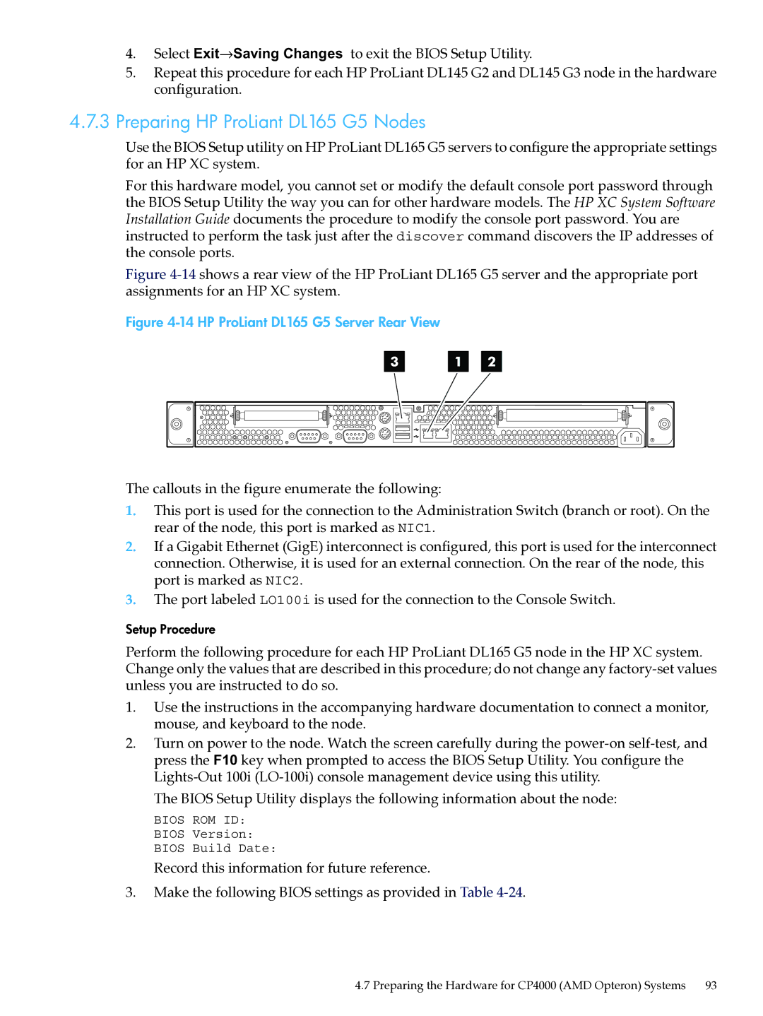
Figure 4-14 shows a rear view of the HP ProLiant DL165 G5 server and the appropriate port assignments for an HP XC system.
Figure 4-14 HP ProLiant DL165 G5 Server Rear View
3 | 1 | 2 |
|
| |||
|
|
|
|
|
|
|
|
|
|
|
|
|
|
|
|
|
|
|
|
|
|
|
|
|
|
|
|
|
|
|
|
The callouts in the figure enumerate the following:
1.This port is used for the connection to the Administration Switch (branch or root). On the rear of the node, this port is marked as NIC1.
2.If a Gigabit Ethernet (GigE) interconnect is configured, this port is used for the interconnect connection. Otherwise, it is used for an external connection. On the rear of the node, this port is marked as NIC2.
3.The port labeled LO100i is used for the connection to the Console Switch.
Setup Procedure
Perform the following procedure for each HP ProLiant DL165 G5 node in the HP XC system. Change only the values that are described in this procedure; do not change any
1.Use the instructions in the accompanying hardware documentation to connect a monitor, mouse, and keyboard to the node.
2.Turn on power to the node. Watch the screen carefully during the
The BIOS Setup Utility displays the following information about the node:
BIOS ROM ID: BIOS Version: BIOS Build Date:
Record this information for future reference.
3.Make the following BIOS settings as provided in Table
4.7 Preparing the Hardware for CP4000 (AMD Opteron) Systems 93