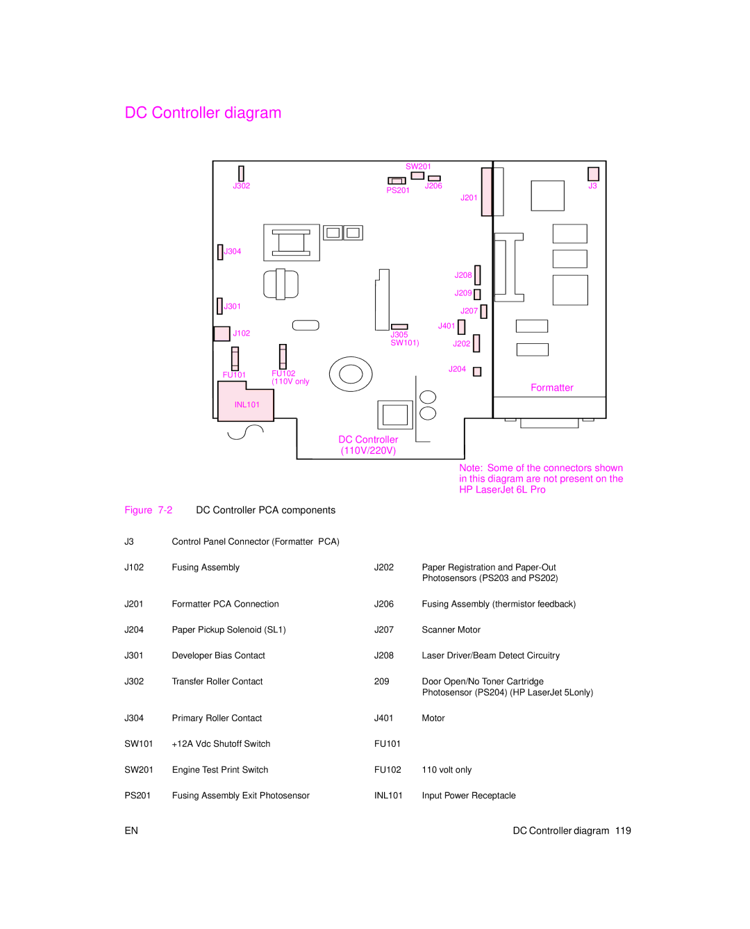
DC Controller diagram
|
|
|
|
| SW201 | ||||
|
|
| |||||||
|
|
|
|
|
|
|
|
|
|
|
|
|
|
|
|
|
|
|
|
J302 |
|
|
|
| J206 | ||||
PS201 |
| ||||||||
|
|
|
|
|
|
| |||
J201
J3 |
J304 |
|
|
|
| J208 |
|
| J209 |
J301 |
| J207 |
|
| |
J102 |
| J401 |
J305 |
| |
| SW101) | J202 |
FU101 | FU102 | J204 |
| ||
| (110V only | Formatter |
|
| |
INL101 |
|
|
DC Controller (110V/220V)
Note: Some of the connectors shown in this diagram are not present on the HP LaserJet 6L Pro
Figure 7-2 DC Controller PCA components
J3 | Control Panel Connector (Formatter PCA) |
|
|
J102 | Fusing Assembly | J202 | Paper Registration and |
|
|
| Photosensors (PS203 and PS202) |
J201 | Formatter PCA Connection | J206 | Fusing Assembly (thermistor feedback) |
J204 | Paper Pickup Solenoid (SL1) | J207 | Scanner Motor |
J301 | Developer Bias Contact | J208 | Laser Driver/Beam Detect Circuitry |
J302 | Transfer Roller Contact | 209 | Door Open/No Toner Cartridge |
|
|
| Photosensor (PS204) (HP LaserJet 5Lonly) |
J304 | Primary Roller Contact | J401 | Motor |
SW101 | +12A Vdc Shutoff Switch | FU101 |
|
SW201 | Engine Test Print Switch | FU102 | 110 volt only |
PS201 | Fusing Assembly Exit Photosensor | INL101 | Input Power Receptacle |
EN | DC Controller diagram 119 |