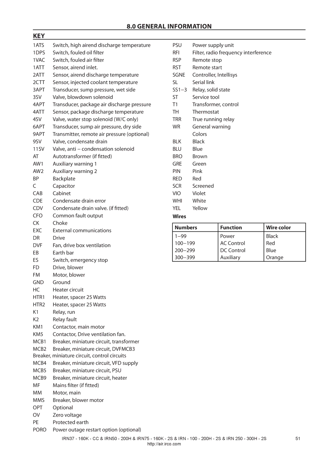
8.0 GENERAL INFORMATION
KEY
1ATS | Switch, high airend discharge temperature | PSU | Power supply unit |
| ||
1DPS | Switch, fouled oil filter | RFI | Filter, radio frequency interference | |||
1VAC | Switch, fouled air filter | RSP | Remote stop |
| ||
1ATT | Sensor, airend inlet. | RST | Remote start |
| ||
2ATT | Sensor, airend discharge temperature | SGNE | Controller, Intellisys |
| ||
2CTT | Sensor, injected coolant temperature | SL | Serial link |
|
| |
3APT | Transducer, sump pressure, wet side | SS1−3 | Relay, solid state |
| ||
3SV | Valve, blowdown solenoid | ST | Service tool |
|
| |
4APT | Transducer, package air discharge pressure | T1 | Transformer, control |
| ||
4ATT | Sensor, package discharge temperature | TH | Thermostat |
|
| |
4SV | Valve, water stop solenoid (W/C only) | TRR | True running relay |
| ||
6APT | Transducer, sump air pressure, dry side | WR | General warning |
| ||
9APT | Transmitter, remote air pressure (optional) |
| Colors |
|
| |
9SV | Valve, condensate drain | BLK | Black |
|
| |
11SV | Valve, anti − condensation solenoid | BLU | Blue |
|
| |
AT | Autotransformer (if fitted) | BRO | Brown |
|
| |
AW1 | Auxiliary warning 1 | GRE | Green |
|
| |
AW2 | Auxiliary warning 2 | PIN | Pink |
|
| |
BP | Backplate | RED | Red |
|
| |
C | Capacitor | SCR | Screened |
|
| |
CAB | Cabinet | VIO | Violet |
|
| |
CDE | Condensate drain error | WHI | White |
|
| |
CDV | Condensate drain valve. (if fitted) | YEL | Yellow |
|
| |
CFO | Common fault output | Wires |
|
|
|
|
CK | Choke |
|
|
|
|
|
Numbers |
| Function | Wire color | |||
EXC | External communications |
| ||||
|
|
|
|
| ||
1−99 |
|
| Power | Black | ||
DR | Drive |
|
| |||
100−199 |
| AC Control | Red | |||
DVF | Fan, drive box ventilation |
| ||||
200−299 |
| DC Control | Blue | |||
EB | Earth bar |
| ||||
300−399 |
| Auxiliary | Orange | |||
ES | Switch, emergency stop |
| ||||
|
|
|
|
| ||
|
|
|
|
| ||
FD | Drive, blower |
|
|
|
|
|
FM | Motor, blower |
|
|
|
|
|
GND | Ground |
|
|
|
|
|
HC | Heater circuit |
|
|
|
|
|
HTR1 | Heater, spacer 25 Watts |
|
|
|
|
|
HTR2 | Heater, spacer 25 Watts |
|
|
|
|
|
K1 | Relay, run |
|
|
|
|
|
K2 | Relay fault |
|
|
|
|
|
KM1 | Contactor, main motor |
|
|
|
|
|
KM5 | Contactor, Drive ventilation fan. |
|
|
|
|
|
MCB1 | Breaker, miniature circuit, transformer |
|
|
|
|
|
MCB2 | Breaker, miniature circuit, DVFMCB3 |
|
|
|
|
|
Breaker, miniature circuit, control circuits |
|
|
|
|
| |
MCB4 | Breaker, miniature circuit, VFD supply |
|
|
|
|
|
MCB5 | Breaker, miniature circuit, PSU |
|
|
|
|
|
MCB9 | Breaker, miniature circuit, heater |
|
|
|
|
|
MF | Mains filter (if fitted) |
|
|
|
|
|
MM | Motor, main |
|
|
|
|
|
MMS | Breaker, blower motor |
|
|
|
|
|
OPT | Optional |
|
|
|
|
|
OV | Zero voltage |
|
|
|
|
|
PE | Protected earth |
|
|
|
|
|
PORO | Power outage restart option (optional) |
|
|
|
|
|
IRN37 - 160K - CC & IRN50 - 200H & IRN75 - 160K - 2S & IRN - 100 - 200H - 2S & IRN 250 - 300H - 2S | 51 |
http://air.irco.com |
|
