8.0GENERAL INFORMATION
8.2INSTALLATION DRAWING− N37/45K−CC & N50/60H−CC − Water Cooled
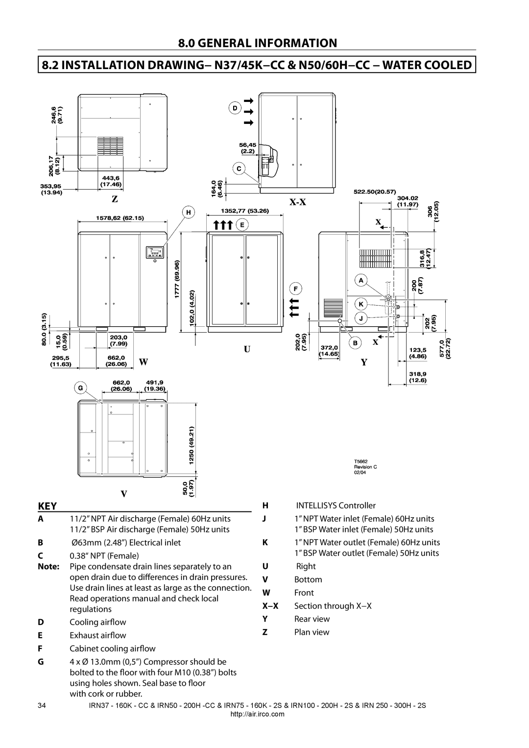
KEY
A11/2” NPT Air discharge (Female) 60Hz units 11/2” BSP Air discharge (Female) 50Hz units
BØ63mm (2.48”) Electrical inlet
C0.38“ NPT (Female)
Note: Pipe condensate drain lines separately to an open drain due to differences in drain pressures. Use drain lines at least as large as the connection. Read operations manual and check local regulations
DCooling airflow
EExhaust airflow
FCabinet cooling airflow
G4 x Ø 13.0mm (0,5”) Compressor should be
bolted to the floor with four M10 (0.38”) bolts using holes shown. Seal base to floor
with cork or rubber.
HINTELLISYS Controller
J1” NPT Water inlet (Female) 60Hz units 1” BSP Water inlet (Female) 50Hz units
K1” NPT Water outlet (Female) 60Hz units 1” BSP Water outlet (Female) 50Hz units
URight
VBottom
WFront
X−X Section through X−X
YRear view
ZPlan view
34IRN37 - 160K - CC & IRN50 - 200H
http://air.irco.com