8.0GENERAL INFORMATION
8.2INSTALLATION DRAWING−N37/45K−CC & N50/60H−CC − Air Cooled
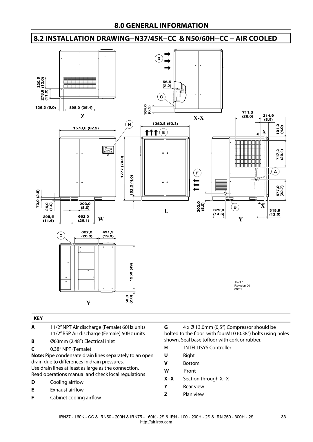
KEY
A | 11/2” NPT Air discharge (Female) 60Hz units | G | 4 x Ø 13.0mm (0,5”) Compressor should be | |
| 11/2” BSP Air discharge (Female) 50Hz units | bolted to the floor with fourM10 (0.38”) bolts using holes | ||
B | Ø63mm (2.48”) Electrical inlet | shown. Seal base tofloor with cork or rubber. | ||
C | 0.38“ NPT (Female) | H | INTELLISYS Controller | |
Note: Pipe condensate drain lines separately to an open | U | Right | ||
drain due to differences in drain pressures. | V | Bottom | ||
Use drain lines at least as large as the connection. | W | Front | ||
Read operations manual and check local regulations | ||||
X−X | Section through X−X | |||
D | Cooling airflow | |||
Y | Rear view | |||
E | Exhaust airflow | |||
Z | Plan view | |||
F | Cabinet cooling airflow | |||
|
| |||
IRN37 - 160K - CC & IRN50 - 200H & IRN75 - 160K - 2S & IRN - 100 - 200H - 2S & IRN 250 - 300H - 2S | 33 |
http://air.irco.com |
|