ELECTRICAL CONNECTIONS
WIRING |
|
|
|
|
|
|
|
|
|
|
|
|
|
| (BLACK) |
|
|
|
|
|
|
| CD CHANGER |
|
|
|
|
|
|
| AND SIRIUS RECEIVER |
|
|
|
|
|
|
| CONNECTOR SOCKET |
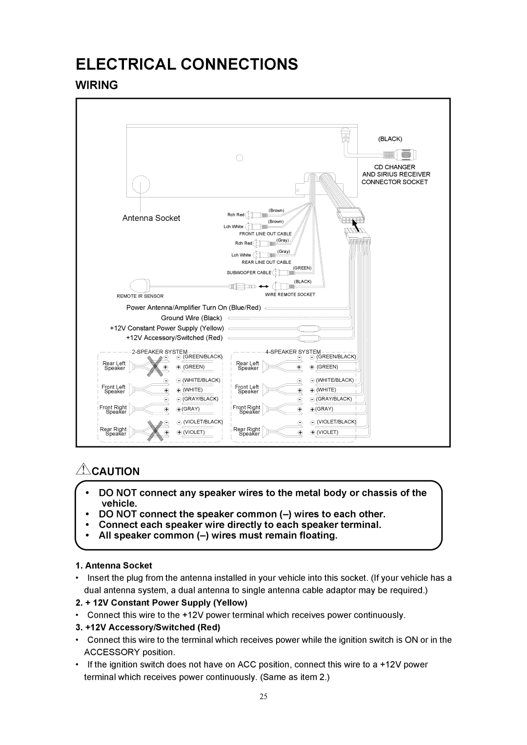
Antenna Socket | Rch Red | (Brown) |
|
|
| ||
|
|
|
| ||||
Lch White | (Brown) |
|
|
| |||
|
|
|
|
|
|
| |
|
|
| FRONT LINE OUT CABLE |
|
|
| |
|
|
| Rch Red | (Gray) |
|
|
|
|
|
|
|
|
|
| |
|
|
| Lch White | (Gray) |
|
|
|
|
|
|
|
|
|
| |
|
|
| REAR LINE OUT CABLE | (GREEN) |
| ||
|
|
| SUBWOOFER CABLE |
| |||
|
|
|
|
|
| ||
|
|
|
|
| (BLACK) |
| |
REMOTE IR SENSOR |
|
| WIRE REMOTE SOCKET |
| |||
Power Antenna/Amplifier Turn On (Blue/Red) |
|
|
|
| |||
| Ground Wire (Black) |
|
|
|
|
| |
+12V Constant Power Supply (Yellow) |
|
|
|
| |||
+12V Accessory/Switched (Red) |
|
|
|
|
| ||
|
| ||||||
Rear Left | - | - (GREEN/BLACK) | Rear Left |
| - | - | (GREEN/BLACK) |
+ | + (GREEN) |
| + | + (GREEN) | |||
Speaker | Speaker |
| |||||
Front Left | - | - (WHITE/BLACK) | Front Left |
| - | - | (WHITE/BLACK) |
+ | + (WHITE) |
| + | + (WHITE) | |||
Speaker | Speaker |
| |||||
Front Right | - | - (GRAY/BLACK) | Front Right |
| - | - | (GRAY/BLACK) |
+ | + (GRAY) |
| + | + (GRAY) | |||
Speaker | Speaker |
| |||||
Rear Right | - | - (VIOLET/BLACK) | Rear Right |
| - | - | (VIOLET/BLACK) |
+ | + (VIOLET) |
| + | + (VIOLET) | |||
Speaker | Speaker |
| |||||
![]() CAUTION
CAUTION
•DO NOT connect any speaker wires to the metal body or chassis of the vehicle.
•DO NOT connect the speaker common
•Connect each speaker wire directly to each speaker terminal.
•All speaker common
1.Antenna Socket
•Insert the plug from the antenna installed in your vehicle into this socket. (If your vehicle has a dual antenna system, a dual antenna to single antenna cable adaptor may be required.)
2. + 12V Constant Power Supply (Yellow)
•Connect this wire to the +12V power terminal which receives power continuously.
3. +12V Accessory/Switched (Red)
•Connect this wire to the terminal which receives power while the ignition switch is ON or in the ACCESSORY position.
•If the ignition switch does not have on ACC position, connect this wire to a +12V power terminal which receives power continuously. (Same as item 2.)
25