Operation
Operation of RGB 118 and RGB 118 PLUS
Front Panel
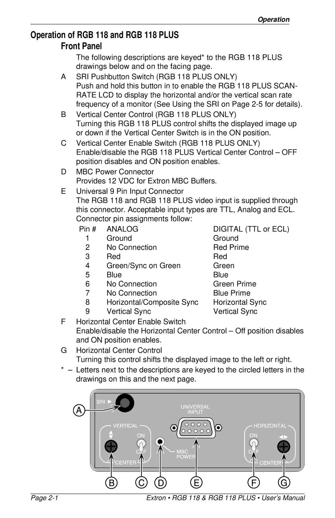
The following descriptions are keyed* to the RGB 118 PLUS drawings below and on the facing page.
ASRI Pushbutton Switch (RGB 118 PLUS ONLY)
Push and hold this button in to enable the RGB 118 PLUS SCAN- RATE LCD to display the horizontal and/or the vertical scan rate frequency of a monitor (See Using the SRI on Page
BVertical Center Control (RGB 118 PLUS ONLY)
Turning this RGB 118 PLUS control shifts the displayed image up or down if the Vertical Center Switch is in the ON position.
CVertical Center Enable Switch (RGB 118 PLUS ONLY) Enable/disable the RGB 118 PLUS Vertical Center Control – OFF position disables and ON position enables.
DMBC Power Connector
Provides 12 VDC for Extron MBC Buffers.
EUniversal 9 Pin Input Connector
The RGB 118 and RGB 118 PLUS video input is supplied through this connector. Acceptable input types are TTL, Analog and ECL. Connector pin assignments follow:
Pin # | ANALOG | DIGITAL (TTL or ECL) |
1 | Ground | Ground |
2 | No Connection | Red Prime |
3 | Red | Red |
4 | Green/Sync on Green | Green |
5 | Blue | Blue |
6 | No Connection | Green Prime |
7 | No Connection | Blue Prime |
8 | Horizontal/Composite Sync | Horizontal Sync |
9 | Vertical Sync | Vertical Sync |
FHorizontal Center Enable Switch
Enable/disable the Horizontal Center Control – Off position disables and ON position enables.
GHorizontal Center Control
Turning this control shifts the displayed image to the left or right.
*– Letters next to the descriptions are keyed to the circled letters in the drawings on this and the next page.
Page | Extron • RGB 118 & RGB 118 PLUS • User’s Manual |