Installation and Operation
Description
The RGB 120p has a Video Bandwidth of 200 MHz and is compatible with any Analog or ECL computer system with a horizontal frequency range of
Installation (See illustration)
1. Turn off computer and its Monitor.
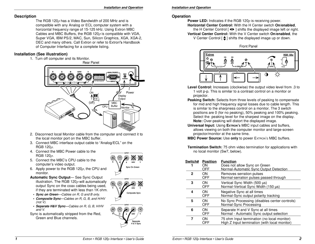
Rear Panel
OUTPUTS |
ON | Power |
| Display |
| Output |
(off) | MBC |
|
CPU | Buffer | Monitor |
|
|
2.Disconnect local Monitor cable from the computer and connect it to the local monitor port on the MBC buffer.
3.Connect MBC interface output cable to “Analog/ECL” on the RGB 120p.
4.Connect the MBC Power cable to the RGB 120p.
5.Connect the MBC’s CPU cable to the computer’s video output.
6. Apply power to the RGB 120p, the CPU and monitor.
Automatic Sync Output— See Sync Output illustration. The RGB 120p will automatically output Sync on the coax cables being used, if they are terminated with less than 1K ohm.
• Sync on
•Composite
(not V).
• Separate H&V
Sync is automatically stripped from the Red,
Green and Blue channels.
Installation and Operation
Operation
Power LED: Indicates if the RGB 120p is receiving power.
Horizontal Center Control: With the H Center switchOn/enabled, the H Center Control [![]()
![]() ] shifts the displayed image left or right.
] shifts the displayed image left or right.
Vertical Center Control: With the V Center switchOn/enabled, the
VCenter Control [![]() ] shifts the displayed image up or down. Front Panel
] shifts the displayed image up or down. Front Panel
| 100% |
| 0 |
| 50% |
V CENTER | PEAK |
Level Control: Increases (clockwise) the output video level from .3 to 1 volt
Peaking Switch: Selects from three levels of peaking to compensate for mid and high frequency signal losses due to cable length. This is similar to the sharpness control on a monitor. The 3 switch positions are 0 (for no peaking), 50% peaking and 100% peaking. Select the peaking level for the sharpest image on the display. Note:
Universal Input: Using EXTRON’S MBC input cables and buffers, allows viewing on both the computer monitor and
MBC Power Source: Use only to power EXTRON’S MBC buffers.
Termination Switch: 75 ohm video termination for applications with no local monitor (Sw7, below).
Switch# | Position | Function | |
1 | ON | Does not allow Sync on Green | |
|
| OFF | |
2 | ON | Removes serration pulses | |
|
| OFF | |
3 | ON | Vertical Sync Width (500 µs) | |
|
| OFF | |
4 | ON | Negative Sync at all times | |
|
| OFF | |
5 | ON | No Sync Processing (disables center controls) | |
|
| OFF | |
6 | ON | Separate H and V Sync at all times | |
|
| OFF | Normal - Automatic Sync output selection |
7 | ON | 75 ohm Input termination (no local monitor) | |
|
| OFF | High Z Input termination (with local monitor) |
1 | Extron • RGB 120p Interface • User’s Guide | Extron • RGB 120p Interface • User’s Guide | 2 |