RGB 160 specifications
The Extron RGB 160 is a high-performance video interface designed for seamlessly integrating RGB video signals into diverse audio-visual systems. Known for its versatility and advanced capabilities, the RGB 160 is particularly suitable for educational institutions, conference rooms, and command-and-control environments.One of the primary features of the Extron RGB 160 is its ability to support multiple video formats. It handles RGBHV, RGBS, RGsB, component video, and even composite video, making it an invaluable asset in environments where various video sources are used. This flexibility ensures that users can connect a variety of devices without the need for additional converters or adapters.
The RGB 160 incorporates Extron’s patented scalar technology, which guarantees high-quality signal processing. This technology ensures that the output video maintains excellent resolution and clarity, regardless of the source's original quality. The device can scale input resolutions up to 1600x1200 at 60Hz, ensuring compatibility with a broad range of projectors and displays. The result is a seamless integration that presents video signals with outstanding fidelity.
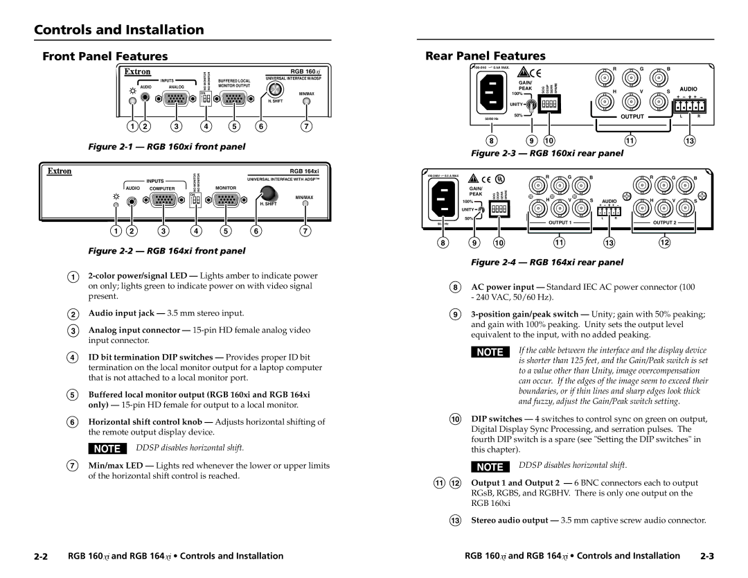
Another noteworthy characteristic of the RGB 160 is its intuitive user interface. The front panel includes an interactive LED display and easily accessible controls, allowing for quick adjustments and monitoring of signal status. Connectivity options include multiple inputs and outputs, facilitating easy switching among various sources. The unit supports both standard analog and digital formats, enhancing its adaptability to different system requirements.
In terms of installation and configuration, the RGB 160 is designed for user-friendly operation. It features a compact form factor, allowing it to be neatly integrated into existing equipment racks. The device is also compatible with Extron's extensive line of control systems, providing integrators with simple automation options.
Moreover, the RGB 160 is engineered with robust build quality, ensuring durability and reliability for long-term operation. Extron's commitment to quality is reflected in the RGB 160, which comes with a comprehensive warranty and support program, further contributing to its reputation as a trusted solution in professional AV applications.
In conclusion, the Extron RGB 160 is a powerful and versatile video interface that stands out for its advanced scaling technology, broad compatibility, and user-friendly design. Its numerous features make it a formidable choice for any setting that demands high-quality RGB video integration.

