RGB 202 Rxi, RGB 202 Rxi VTG specifications
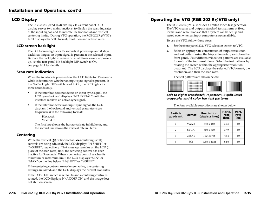
The Extron RGB 202 Rxi VTG is a highly efficient, versatile video signal processor that offers robust functionality tailored for professional AV applications. This device is designed to handle RGB video and is particularly well-suited for integration into complex AV systems, providing exceptional image quality and ease of use.One of the standout features of the RGB 202 Rxi is its ability to accommodate multiple video formats, including high-resolution RGBHV, RGBS, and even component video signals. This flexibility makes it an ideal choice for environments where varying sources need to be managed seamlessly. The device can output standard video formats up to 1920x1200, ensuring compatibility with a wide range of display technologies.
In addition to its impressive video handling capabilities, the RGB 202 Rxi incorporates advanced signal processing technologies. The built-in video scaling technology optimizes output resolutions, ensuring that images are displayed clearly and without distortion. This is especially important in environments where image detail is critical, such as in educational institutions, corporate settings, or command and control centers.
Another noteworthy characteristic of the RGB 202 Rxi is its extensive connectivity options. The device features multiple input and output connectors, including RGBHV, RS-232, and composite video, facilitating easy integration into existing systems. The integrated Electra™ technology enhances the unit's signal processing abilities, providing sharp and high-quality outputs regardless of the source material.
User-friendliness is also a key design element of the RGB 202 Rxi. Its intuitive front panel controls and LCD interface simplify operation, while the capability for remote control via RS-232 adds an extra layer of convenience for system operators. Additionally, with Extron’s software, operators can customize settings, manage presets, and monitor the device easily.
Overall, the Extron RGB 202 Rxi VTG represents a powerful solution for professional AV applications that require high-quality RGB video processing. Its combination of advanced technology, versatility, and user-friendly operation makes it a reliable choice for professionals who demand performance and flexibility in their AV systems. Whether in conference rooms or educational settings, this device is designed to meet the needs of dynamic and demanding environments.

