Installation and Operation, cont’d

5. For through-surface mounting (all except TP R 15HD A),

insert four #8 wood screws through the bracket and into the four pilot holes. Tighten all four screws to secure the receiver in place.

6. For under-surface mounting, insert #8 wood screws into the four pilot holes. Tighten each screw into the mounting surface until just less than 1/4” of the screw protrudes.

7. For under-surface mounting, align the mounting screws with the slots in the brackets and place the receiver against the surface, with the screws through the bracket slots.

8. For under-surface mounting, slide the receiver slightly forward or back, then tighten all four screws to secure the switcher in place.

Projector mounting

All of the receiver models can be mounted on a projector bracket using the appropriate optional mounting bracket, Extron’s Mini Projector Mounting Kit (part #70-217-01)

(TP R 15 HD A) or Projector Mounting Kit (part #70-077-04) (all other models).

Secure the mounting bracket to the receiver using two machine screws in the side of the receiver (TP R 15HD A) or the three #8 machine screws provided (all other models). Secure the receiver to a projector mount or other surface by inserting the mounting bolt through the bracket’s slotted hole (figure 2-6).


Mounting

Projector

Bolt


Mounting

TP R 15HD A

Bracket


Mounting

Projector

Bolt


Mounting

TP R AV

Bracket

Figure 2-6 — Projector bracket mounting a receiver

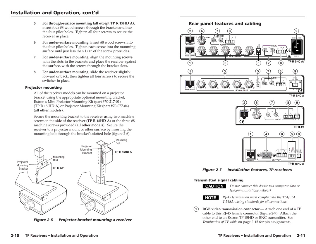
Rear panel features and cabling

2

6

7


8


9


A-V AUDIO


VIDEO

A

L

B

R


100-240V

0.3A


R

L


A-V INPUT


AUDIO


SOG C SYNC

AUDIO


B


L

R


A


R

L


RGB INPUT

R

G


B

H/HV

V


RGB OUTPUT


50/60 Hz


1

3

5

7


8

TP R BNC AV


1

3

5

7


8

9


SOG SYNCC

AUDIO

L

B

POWER


R


A


15V .5A DC


R

L


RGB INPUT

R

G

B

H/HV

V


RGB OUTPUT


TP R BNC A

2

6

7

8

9


A-V OUTPUT


A-V INPUT

VIDEO

A

B


L

R

POWER


15V .5A DC


R

L


AUDIO


TP R AV


1

4

8

5

9


RGB

L R

SYNCC SOG VIDEOC

N/C 15V


AUDIO


POWER


.34A MAX


AV INPUT


OUTPUT


TP R 15HD A

Figure 2-7 — Installation features, TP receivers


Transmitted signal cabling


CAUTION

Do not connect this device to a computer data or


telecommunications network


RJ-45 termination must comply with the TIA/EIA

T 568A wiring standards for all connections.

1RGB video transmission connector — Attach one end of a TP cable to this RJ-45 female connector (figure 2-7). Attach the other end to an Extron TP 15HD or BNC transmitter. See Termination of TP cable on page 2-15 for pin assignments.

2-10 TP Receivers • Installation and Operation

TP Receivers • Installation and Operation 2-11

Page 12
Image 12
Extron electronic TP R BNC A, TP R 15HD A Rear panel features and cabling, Projector mounting, Transmitted signal cabling

TP R AV, TP R 15HD A, TP R BNC A specifications

Extron Electronics has long been a leader in the field of audiovisual technology, offering a range of products designed to meet the needs of various applications. One such product is the Extron TP R BNC A, a high-performance, twisted pair receiver designed for the transmission of RGBHV signals over long distances. This device is essential for managing and distributing video signals in environments like classrooms, auditoriums, and conference rooms.

One of the standout features of the TP R BNC A is its ability to transmit RGBHV video signals using standard twisted pair cabling with minimal distortion, making it an ideal solution for long cable runs. Its innovative technology ensures that the integrity of the signal is maintained, providing high-quality video output even over extended distances.

The TP R BNC A is equipped with highly advanced signal processing capabilities, allowing it to equalize and amplify incoming signals for optimal performance. This feature significantly reduces the risk of signal degradation, ensuring that users receive the best possible image quality. Additionally, the device supports resolutions up to 1920x1200, making it suitable for modern high-definition displays.

Another key characteristic of the TP R BNC A is its versatility in integration. The device includes multiple output options, accommodating various types of connectors for seamless connectivity with a wide range of equipment. Its flexibility allows users to adapt the setup to suit their specific needs, whether connecting to legacy systems or modern AV devices.

The compact design of the TP R BNC A also deserves mention. Its small form factor facilitates easy installation in tight spaces, while the rack-mountable option further extends its adaptability for different configurations. Moreover, the unit features built-in LED indicators for easy status monitoring, allowing technicians to quickly assess its operational state.

In terms of compatibility, the TP R BNC A works seamlessly with Extron’s extensive portfolio of products, including switchers, scalers, and matrix switchers. This compatibility ensures a cohesive operational environment, simplifying system integration and management.

Overall, the Extron TP R BNC A represents a culmination of advanced engineering and practical design, making it a vital component in any professional AV setup. Its high-performance capabilities, combined with flexible installation options and remarkable signal integrity, position it as an indispensable tool for audiovisual professionals seeking reliability and quality in their projects.