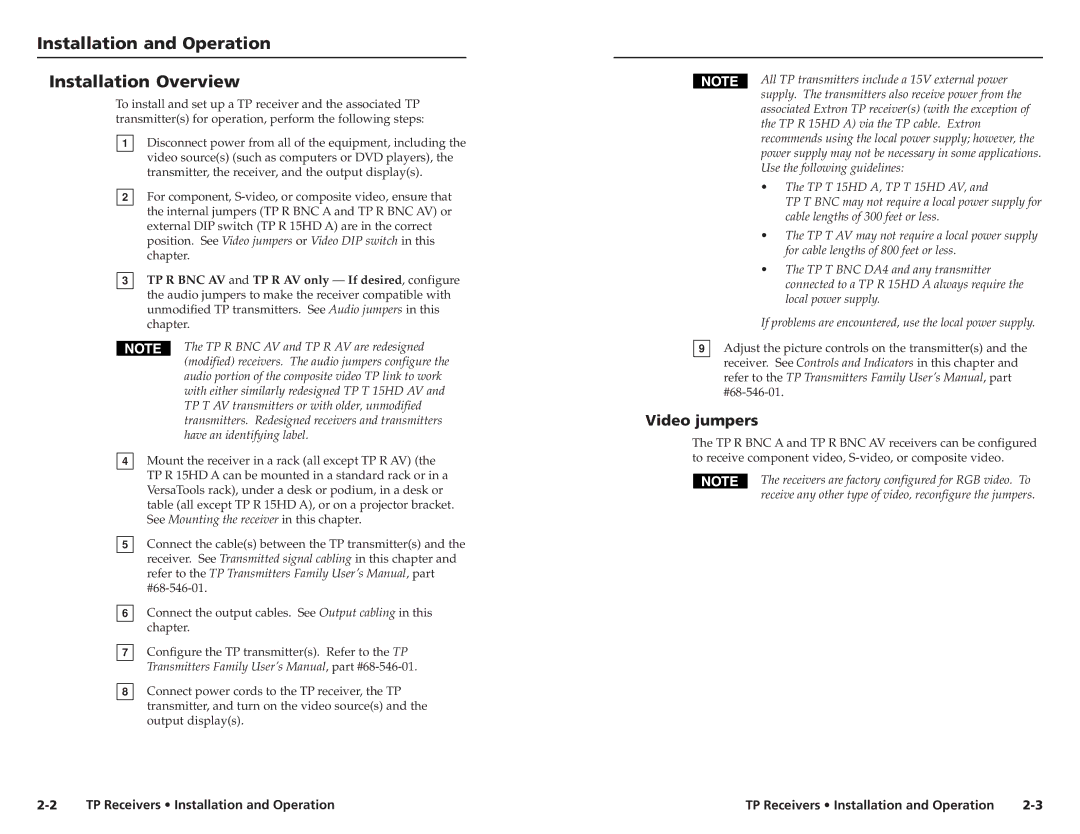
TP R AV, TP R 15HD A, TP R BNC A specifications
Extron Electronics has long been a leader in the field of audiovisual technology, offering a range of products designed to meet the needs of various applications. One such product is the Extron TP R BNC A, a high-performance, twisted pair receiver designed for the transmission of RGBHV signals over long distances. This device is essential for managing and distributing video signals in environments like classrooms, auditoriums, and conference rooms.One of the standout features of the TP R BNC A is its ability to transmit RGBHV video signals using standard twisted pair cabling with minimal distortion, making it an ideal solution for long cable runs. Its innovative technology ensures that the integrity of the signal is maintained, providing high-quality video output even over extended distances.
The TP R BNC A is equipped with highly advanced signal processing capabilities, allowing it to equalize and amplify incoming signals for optimal performance. This feature significantly reduces the risk of signal degradation, ensuring that users receive the best possible image quality. Additionally, the device supports resolutions up to 1920x1200, making it suitable for modern high-definition displays.
Another key characteristic of the TP R BNC A is its versatility in integration. The device includes multiple output options, accommodating various types of connectors for seamless connectivity with a wide range of equipment. Its flexibility allows users to adapt the setup to suit their specific needs, whether connecting to legacy systems or modern AV devices.
The compact design of the TP R BNC A also deserves mention. Its small form factor facilitates easy installation in tight spaces, while the rack-mountable option further extends its adaptability for different configurations. Moreover, the unit features built-in LED indicators for easy status monitoring, allowing technicians to quickly assess its operational state.
In terms of compatibility, the TP R BNC A works seamlessly with Extron’s extensive portfolio of products, including switchers, scalers, and matrix switchers. This compatibility ensures a cohesive operational environment, simplifying system integration and management.
Overall, the Extron TP R BNC A represents a culmination of advanced engineering and practical design, making it a vital component in any professional AV setup. Its high-performance capabilities, combined with flexible installation options and remarkable signal integrity, position it as an indispensable tool for audiovisual professionals seeking reliability and quality in their projects.

