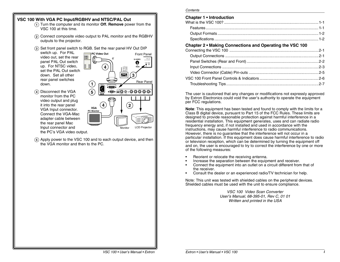
VSC 100 With VGA PC Input/RGBHV and NTSC/PAL Out
1Turn the computer and its monitor Off. Remove power from the VSC 100 at this time.
2Connect composite video output to PAL monitor and the RGBHV outputs to the projector.
3Set front panel switch to RGB. Set the rear panel HV Out DIP
switch up. For PAL | PC Video Out |
|
|
|
| Front Panel | |||
video out, set the rear |
|
|
|
| |||||
|
|
| 6' |
|
|
| VSC 100 | ||
panel PAL Out switch |
|
|
|
|
|
| SCAN CONVERTER | ||
|
|
|
|
|
|
|
| ||
|
|
|
|
|
|
|
| LOCK | |
up. For NTSC video, |
|
| 4 |
|
| SPARE HV OUT | PAL OUT 75 OHM | RGB | RGB |
|
|
|
|
| |||||
|
|
|
|
|
| ||||
set the PAL Out switch |
|
|
|
|
|
|
| ||
|
|
|
|
|
|
| 3 |
| |
down. Set all other |
|
|
|
|
|
|
|
| |
rear panel switches | 1 |
|
|
|
|
|
| Rear Panel | |
down. |
|
|
|
|
|
| |||
0.9A | INPUTS |
|
|
|
|
| |||
50/60 Hz |
|
|
|
|
|
| |||
|
|
|
|
|
|
|
| ||
4 Disconnect the VGA |
|
|
| MAC | SPARE HV OUT PAL OUT | 75 OHM |
| OUTPUTS |
|
5 |
|
|
|
|
|
| |||
|
| VGA |
| COMPOSITE | GB | H/HVV | |||
monitor from the PC |
|
|
|
|
|
|
|
|
|
video output and plug |
| 4 |
|
|
|
|
|
| |
it into the rear panel | VGA |
|
|
| 2 |
|
| ||
VGA Input connector. |
|
|
|
|
|
|
|
| |
PC Monitor |
|
|
|
|
|
|
|
| |
Connect the |
|
|
|
|
|
|
|
|
|
adapter cable between |
|
|
|
|
|
|
|
|
|
the rear panel Mac |
|
|
|
|
|
|
|
|
|
Input connector and |
|
|
|
|
| Monitor | LCD Projector | ||
the PC’s VGA video output.
5Apply power to the VSC 100 and to each output device, and then the VGA monitor and then to the PC.
Contents
Chapter 1 • Introduction
What is the VSC 100? | |
Features | |
Output Formats | |
Specifications |
Chapter 2 • Making Connections and Operating the VSC 100
Connecting the VSC 100 | |
Output Connections | |
Panel Switches (Rear and Front) | |
Input Connections | |
Video Connector (Cable) | |
VSC 100 Front Panel Controls & Indicators | |
Troubleshooting Tips |
The user is cautioned that any changes or modifications not expressly approved by Extron Electronics could void the user’s authority to operate the equipment per FCC regulations.
Note: This equipment has been tested and found to comply with the limits for a Class B digital device, pursuant to Part 15 of the FCC Rules. These limits are designed to provide reasonable protection against harmful interference in a residential installation. This equipment generates, uses and can radiate radio frequency energy and, if not installed and used in accordance with the instructions, may cause harmful interference to radio communications. However, there is no guarantee that the interference will not occur in a particular installation. If this equipment does cause harmful interference to radio or television reception, which can be determined by turning the equipment off and on, the user is encouraged to try to correct the interference by one or more of the following measures:
•Reorient or relocate the receiving antenna.
•Increase the separation between the equipment and receiver.
•Connect the equipment into an outlet on a circuit different from that of the receiver.
•Consult the dealer or an experienced radio/TV technician for help.
Note: This unit was tested with shielded cables on the peripheral devices. Shielded cables must be used with the unit to ensure compliance.
VSC 100 Video Scan Converter
User’s Manual,
Written and printed in the USA
VSC 100 • User’s Manual • Extron | Extron • User’s Manual • VSC 100 | i |
