Fairchild AN-7511 manual Latch-Up Hints, Kinks and Caveats, Forward-Bias Latch-Up

Models: AN-7511

1 13
Download 13 pages 45.76 Kb
Page 11
Image 11

Application Note 7511

Latch-Up: Hints, Kinks and Caveats

The IGT is a rugged device, requiring no snubber network when operating within its published safe-operating-area (SOA) ratings. Within the SOA, the gate emitter voltage controls the collector current. In fact, the IGT can conduct three to four times the published maximum current if it’s in the ON state and the junction temperature is +150oC maximum.

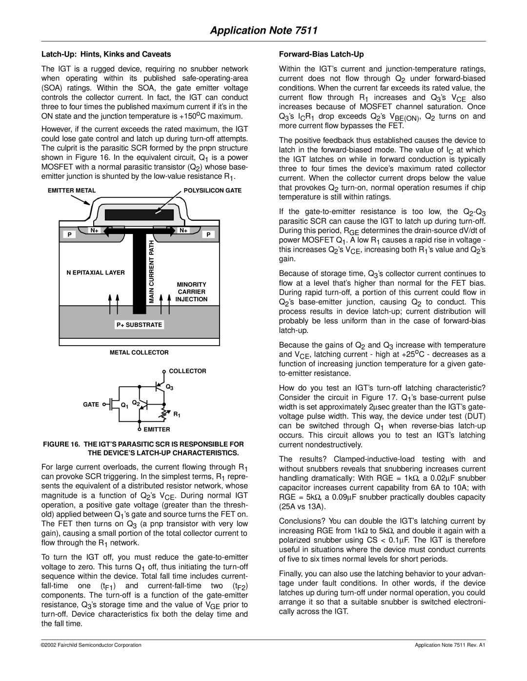
However, if the current exceeds the rated maximum, the IGT could lose gate control and latch up during turn-off attempts. The culprit is the parasitic SCR formed by the pnpn structure shown in Figure 16. In the equivalent circuit, Q1 is a power MOSFET with a normal parasitic transistor (Q2) whose base- emitter junction is shunted by the low-value resistance R1.

EMITTER METAL

POLYSILICON GATE

N+


N+

P


P


PATH


N EPITAXIAL LAYER

CURRENT


MINORITY


MAIN


CARRIER


INJECTION

P+ SUBSTRATE


METAL COLLECTOR

COLLECTOR


Q3

GATE


Q1 Q2


R1


EMITTER


FIGURE 16. THE IGT’S PARASITIC SCR IS RESPONSIBLE FOR THE DEVICE’S LATCH-UP CHARACTERISTICS.

For large current overloads, the current flowing through R1 can provoke SCR triggering. In the simplest terms, R1 repre- sents the equivalent of a distributed resistor network, whose magnitude is a function of Q2’s VCE. During normal IGT operation, a positive gate voltage (greater than the thresh- old) applied between Q1’s gate and source turns the FET on. The FET then turns on Q3 (a pnp transistor with very low gain), causing a small portion of the total collector current to flow through the R1 network.

To turn the IGT off, you must reduce the gate-to-emitter voltage to zero. This turns Q1 off, thus initiating the turn-off sequence within the device. Total fall time includes current- fall-time one (tF1) and current-fall-time two (tF2) components. The turn-off is a function of the gate-emitter resistance, Q3’s storage time and the value of VGE prior to turn-off. Device characteristics fix both the delay time and the fall time.

Forward-Bias Latch-Up

Within the IGT’s current and junction-temperature ratings, current does not flow through Q2 under forward-biased conditions. When the current far exceeds its rated value, the current flow through R1 increases and Q3’s VCE also increases because of MOSFET channel saturation. Once

Q3’s ICR1 drop exceeds Q2’s VBE(ON), Q2 turns on and more current flow bypasses the FET.

The positive feedback thus established causes the device to latch in the forward-biased mode. The value of IC at which the IGT latches on while in forward conduction is typically three to four times the device’s maximum rated collector current. When the collector current drops below the value that provokes Q2 turn-on, normal operation resumes if chip temperature is still within ratings.

If the gate-to-emitter resistance is too low, the Q2-Q3parasitic SCR can cause the IGT to latch up during turn-off. During this period, RGE determines the drain-source dV/dt of power MOSFET Q1. A low R1 causes a rapid rise in voltage - this increases Q2’s VCE, increasing both R1’s value and Q2’s gain.

Because of storage time, Q3’s collector current continues to flow at a level that’s higher than normal for the FET bias. During rapid turn-off, a portion of this current could flow in Q2’s base-emitter junction, causing Q2 to conduct. This process results in device latch-up; current distribution will probably be less uniform than in the case of forward-bias latch-up.

Because the gains of Q2 and Q3 increase with temperature and VCE, latching current - high at +25oC - decreases as a function of increasing junction temperature for a given gate- to-emitter resistance.

How do you test an IGT’s turn-off latching characteristic? Consider the circuit in Figure 17. Q1’s base-current pulse width is set approximately 2sec greater than the IGT’s gate- voltage pulse width. This way, the device under test (DUT) can be switched through Q1 when reverse-bias latch-up occurs. This circuit allows you to test an IGT’s latching current nondestructively.

The results? Clamped-inductive-load testing with and without snubbers reveals that snubbering increases current handling dramatically: With RGE = 1k, a 0.02F snubber capacitor increases current capability from 6A to 10A; with RGE = 5k, a 0.09F snubber practically doubles capacity (25A vs 13A).

Conclusions? You can double the IGT’s latching current by increasing RGE from 1kto 5k, and double it again with a polarized snubber using CS < 0.1F. The IGT is therefore useful in situations where the device must conduct currents of five to six times normal levels for short periods.

Finally, you can also use the latching behavior to your advan- tage under fault conditions. In other words, if the device latches up during turn-off under normal operation, you could arrange it so that a suitable snubber is switched electroni- cally across the IGT.

©2002 Fairchild Semiconductor Corporation

Application Note 7511 Rev. A1

Page 11
Image 11
Fairchild AN-7511 manual Latch-Up Hints, Kinks and Caveats, Forward-Bias Latch-Up

AN-7511 specifications

The Fairchild AN-7511 is a versatile, twin-engine turboprop aircraft designed for a myriad of military applications, including cargo transport, surveillance, and personnel movement. Developed by Fairchild Aircraft in the 1970s, the AN-7511 represents a significant evolution in tactical airlift capabilities, aimed at meeting the diverse needs of the United States Armed Forces and allied nations.

One of the standout features of the AN-7511 is its impressive cargo capacity. The aircraft can carry up to 10 tons of cargo, making it suitable for transporting supplies, equipment, and even troops in various operational scenarios. Its rear ramp design facilitates rapid loading and unloading, which is crucial in military operations where time can be of the essence.

The AN-7511 is powered by two turboprop engines, which provide a combination of efficiency and reliability. These engines offer superior performance at various altitudes and are designed to operate in diverse environmental conditions. The aircraft’s range allows it to execute long-distance missions without the need for frequent refueling, which is vital for sustained operations in remote areas.

In terms of technologies, the AN-7511 features advanced avionics that enhance navigation and situational awareness for the crew. These systems incorporate modern instruments that ensure safe flight operations, even in challenging weather conditions. The cockpit layout is designed for ease of use, enabling pilots to maintain focus on mission objectives.

Another notable characteristic of the AN-7511 is its rugged construction. The airframe is built to endure the rigors of military flights, including rough landings on unpaved airstrips. This durability is complemented by a relatively short takeoff and landing distance, allowing the aircraft to operate in austere environments.

Moreover, the AN-7511 can be equipped with various mission-specific systems, such as surveillance pods or electronic warfare equipment, making it adaptable for different roles. This flexibility extends the operational capabilities of the aircraft, enabling it to fulfill multiple mission types in support of military objectives.

In summary, the Fairchild AN-7511 is a robust and adaptable aircraft that combines advanced technologies with military practicality. Its cargo capacity, range, reliability, and operational flexibility make it a valuable asset for any airlift or tactical operation, ensuring that it remains a critical component of military aviation efforts.