Fairchild AN-7511 manual Use 6-Step Drive For Speed-InvariantTorque

Models: AN-7511

1 13
Download 13 pages 45.76 Kb
Page 8
Image 8

Application Note 7511

Use 6-Step Drive For Speed-InvariantTorque

Figure 10A shows the inverter circuit configured for this example. Diodes D1 through D6 carry the same peak current as the IGTs; consequently, they’re rated to handle peak cur- rents of at least 8.766A. However, they only conduct for a short time (15o to 20o of 180o), so their average-current requirement is relatively small.

External circuitry can control the IGT’s current fall time. Resistor R controls tF1 Figure 10B; there's no way to control tF2, an inherent characteristic of the selected IGT. In this example, a 4.7-kgate-to-emitter resistor provides the appropriate fall time. The choice of current-limiting inductor L1 is based on the IGT’s overload-current rating and the action time (the sum of the sensor’s sensing and response time and the IGT’s turn-off time) in fault conditions.

You could use a set of flip flops and a multivibrator to gener- ate the necessary drive pulses and the corresponding 120o× delay between the three phases in Figure 10’s circuit. A volt- age-controlled oscillator serves to change the inverter’s out- put frequency. In this circuit, IGTs Q1, Q3 and Q5 require isolated gate drive; the drive for Q2, Q4 and Q6 can be referred to common. If you use optocouplers for isolation, you’ll need three isolated or bootstrap power supplies (in addition to the 5V and 24V power supplies) to drive the IGTs. Another alternative is to use transformer coupling.

165o Conduction Prevents Shoot-Through

Consider, however, using Figure 11A’s novel, low-cost cir- cuit. It uses a piezo coupler to drive the isolated IGT. As noted, the coupler needs a high-frequency square wave to induce mechanical oscillations in its primary side. The 555 oscillator provides the necessary 108-kHz waveform; its out- put is gated according to the required timing logic and then applied to the piezo coupler’s primary. The coupler’s rectified output drives the IGT’s gate; the 4.7kW gate-to-emitter resis- tor provides a discharge path for CGE during the IGT’s turn- off. The circuit’s logic-timing diagram is shown in Figure 11B.

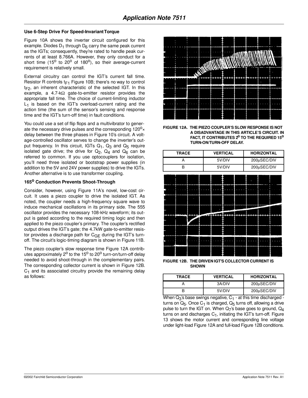
The piezo coupler’s slow response time Figure 12A contrib- utes approximately 2o to the 15o to 20o turn-on/turn-off delay needed to avoid shoot-through in the complementary pairs. The corresponding collector current is shown in Figure 12B. C1 and its associated circuitry provide the remaining delay as follows:

FIGURE 12A. THE PIEZO COUPLER’S SLOW RESPONSE IS NOT A DISADVANTAGE IN THIS ARTICLE’S CIRCUIT. IN FACT, IT CONTRIBUTES 2o TO THE REQUIRED 15o

TURN-ON/TURN-OFF DELAY.

TRACE

VERTICAL

HORIZONTAL


A

5V/DIV

200SEC/DIV


B

5V/DIV

200SEC/DIV


FIGURE 12B. THE DRIVEN IGT'S COLLECTOR CURRENT IS SHOWN

TRACE

VERTICAL

HORIZONTAL


A

3A/DIV

200SEC/DIV


B

5V/DIV

200SEC/DIV


When Q3’s base swings negative, C1 - at this time discharged - turns on Q5. Once C1 is charged, Q5 turns off, allowing a drive pulse to turn the IGT on. When Q7’s base goes to ground, Q4 turns on and discharges C1, initiating the IGT’s turn-off. Figure 13 shows the motor current and corresponding line voltage under light-load Figure 12A and full-load Figure 12B conditions.

©2002 Fairchild Semiconductor Corporation

Application Note 7511 Rev. A1

Page 8
Image 8
Fairchild AN-7511 manual Use 6-Step Drive For Speed-InvariantTorque, 165o Conduction Prevents Shoot-Through

AN-7511 specifications

The Fairchild AN-7511 is a versatile, twin-engine turboprop aircraft designed for a myriad of military applications, including cargo transport, surveillance, and personnel movement. Developed by Fairchild Aircraft in the 1970s, the AN-7511 represents a significant evolution in tactical airlift capabilities, aimed at meeting the diverse needs of the United States Armed Forces and allied nations.

One of the standout features of the AN-7511 is its impressive cargo capacity. The aircraft can carry up to 10 tons of cargo, making it suitable for transporting supplies, equipment, and even troops in various operational scenarios. Its rear ramp design facilitates rapid loading and unloading, which is crucial in military operations where time can be of the essence.

The AN-7511 is powered by two turboprop engines, which provide a combination of efficiency and reliability. These engines offer superior performance at various altitudes and are designed to operate in diverse environmental conditions. The aircraft’s range allows it to execute long-distance missions without the need for frequent refueling, which is vital for sustained operations in remote areas.

In terms of technologies, the AN-7511 features advanced avionics that enhance navigation and situational awareness for the crew. These systems incorporate modern instruments that ensure safe flight operations, even in challenging weather conditions. The cockpit layout is designed for ease of use, enabling pilots to maintain focus on mission objectives.

Another notable characteristic of the AN-7511 is its rugged construction. The airframe is built to endure the rigors of military flights, including rough landings on unpaved airstrips. This durability is complemented by a relatively short takeoff and landing distance, allowing the aircraft to operate in austere environments.

Moreover, the AN-7511 can be equipped with various mission-specific systems, such as surveillance pods or electronic warfare equipment, making it adaptable for different roles. This flexibility extends the operational capabilities of the aircraft, enabling it to fulfill multiple mission types in support of military objectives.

In summary, the Fairchild AN-7511 is a robust and adaptable aircraft that combines advanced technologies with military practicality. Its cargo capacity, range, reliability, and operational flexibility make it a valuable asset for any airlift or tactical operation, ensuring that it remains a critical component of military aviation efforts.