Application Note 7511

Piezoelectric Couplers Provide 4-kV Isolation

Using a high-frequency oscillator for pulse-train drive Figure 6B yields unlimited on-time capability. However, the scheme requires an oscillator that can be turned on and off by the control logic. A diode or zener clamp across the trans- former’s primary will limit leakage-inductance flyback effects.

age-doubler circuitry improves the turn-on time and also pro- vides long on-time capability. Although this design uses only a 5V supply on the primary side of a standard trigger trans- former, it provides 15V gate-to-emitter voltage.

To optimize transformer efficiency, make the pulses’ voltage x time products equal for both the On and the Off pulses. In situations where the line voltage generates the drive power, a simple relaxation oscillator using a programmable unijunc- tion transistor can derive its power directly from the line to provide a pulse train to the IGT gate.

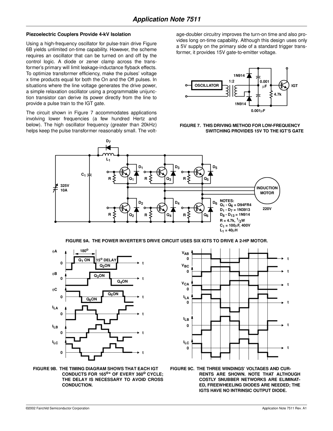
The circuit shown in Figure 7 accommodates applications involving lower frequencies (a few hundred Hertz and

OSCILLATOR

1N914


1:2

0.001

IGT


F


4.7k

1N914


0.001F


below). The high oscillator frequency (greater than 20kHz) helps keep the pulse transformer reasonably small. The volt-

FIGURE 7. THIS DRIVING METHOD FOR LOW-FREQUENCY SWITCHING PROVIDES 15V TO THE IGT’S GATE

D7


L1


D1


D3

D5


C1

Q1


Q3


Q5


R

R

R


325V


INDUCTION

10A


MOTOR


D2


D4

D6

NOTES:


Q

- Q = D94FR4


1

6

220V

R


D1 - D7 = 1N3913

Q2

R

Q4

R

Q6

D8 - D13 = 1N914


R = 4.7k, 1/ W


2


C1 = 100F, 400V


L1 = 40H


FIGURE 9A. THE POWER INVERTER’S DRIVE CIRCUIT USES SIX IGTS TO DRIVE A 2-HP MOTOR.

φA

180o


VAB


Q

1

ON

15o DELAY


0

t


0


t


Q2ON


VBC


φB


Q3ON


0

t


0


t


Q4ON


VCA

t


φC


0


0


Q5ON

ILA


Q6ON

t


0

t


ILA

0

t

ILB


0


t

ILB


0

t

ILC


ILC


0

t

0

t


FIGURE 9B. THE TIMING DIAGRAM SHOWS THAT EACH IGT CONDUCTS FOR 165OF EVERY 360o CYCLE; THE DELAY IS NECESSARY TO AVOID CROSS CONDUCTION.

FIGURE 9C. THE THREE WINDINGS’ VOLTAGES AND CUR- RENTS ARE SHOWN. NOTE THAT ALTHOUGH COSTLY SNUBBER NETWORKS ARE ELIMINAT- ED, FREEWHEELING DIODES ARE NEEDED; THE IGTS HAVE NO INTRINSIC OUTPUT DIODE.

©2002 Fairchild Semiconductor Corporation

Application Note 7511 Rev. A1

Page 5
Image 5
Fairchild AN-7511 manual Piezoelectric Couplers Provide 4-kV Isolation

AN-7511 specifications

The Fairchild AN-7511 is a versatile, twin-engine turboprop aircraft designed for a myriad of military applications, including cargo transport, surveillance, and personnel movement. Developed by Fairchild Aircraft in the 1970s, the AN-7511 represents a significant evolution in tactical airlift capabilities, aimed at meeting the diverse needs of the United States Armed Forces and allied nations.

One of the standout features of the AN-7511 is its impressive cargo capacity. The aircraft can carry up to 10 tons of cargo, making it suitable for transporting supplies, equipment, and even troops in various operational scenarios. Its rear ramp design facilitates rapid loading and unloading, which is crucial in military operations where time can be of the essence.

The AN-7511 is powered by two turboprop engines, which provide a combination of efficiency and reliability. These engines offer superior performance at various altitudes and are designed to operate in diverse environmental conditions. The aircraft’s range allows it to execute long-distance missions without the need for frequent refueling, which is vital for sustained operations in remote areas.

In terms of technologies, the AN-7511 features advanced avionics that enhance navigation and situational awareness for the crew. These systems incorporate modern instruments that ensure safe flight operations, even in challenging weather conditions. The cockpit layout is designed for ease of use, enabling pilots to maintain focus on mission objectives.

Another notable characteristic of the AN-7511 is its rugged construction. The airframe is built to endure the rigors of military flights, including rough landings on unpaved airstrips. This durability is complemented by a relatively short takeoff and landing distance, allowing the aircraft to operate in austere environments.

Moreover, the AN-7511 can be equipped with various mission-specific systems, such as surveillance pods or electronic warfare equipment, making it adaptable for different roles. This flexibility extends the operational capabilities of the aircraft, enabling it to fulfill multiple mission types in support of military objectives.

In summary, the Fairchild AN-7511 is a robust and adaptable aircraft that combines advanced technologies with military practicality. Its cargo capacity, range, reliability, and operational flexibility make it a valuable asset for any airlift or tactical operation, ensuring that it remains a critical component of military aviation efforts.