Application Note 7511

Polyphase motors, controlled by solid-state, adjustable-fre- quency ac drives, are used extensively in pumps, conveyors, mills, machine tools and robotics applications. The specific con- trol method could be either 6-step or pulse-width modulation. This section describes a 6-step drive that uses some of the pre- viously discussed drive techniques (see page 11, “Latch-Up: Hints, Kinks and Caveats”).

Figure 8 defines the drive’s block diagram. A 3-phase rectifier converts the 220V ac to dc; the switching regulator varies the output voltage to the IGT inverter. At the regulator’s output, a large filter capacitor provides a stiff voltage supply to the inverter.

The motor used in this example has a low slip characteristic and is therefore very efficient. You can change the motor’s speed by varying the inverter’s frequency. As the frequency increases, however, the motor’s air-gap flux diminishes, reduc- ing developed-torque capability. You can maintain the flux at a constant level (as in a dc shunt motor) if you also vary the volt- age so the V/F ratio remains constant.

Fiber-Optic Drive Eliminates Interference

In the example given, the switching regulator varies the IGT inverter’s output by controlling its dc input; the voltage-con- trolled oscillator (VCO) adjusts the inverter’s switching fre- quency, thereby varying the output frequency. The VCO also drives the 3-phase logic that provides properly timed pulsed outputs to the piezo couplers that directly drive the IGT.

Sensing the dc current in the negative rail and inhibiting the gate signal protect the IGT from overload and shoot-through

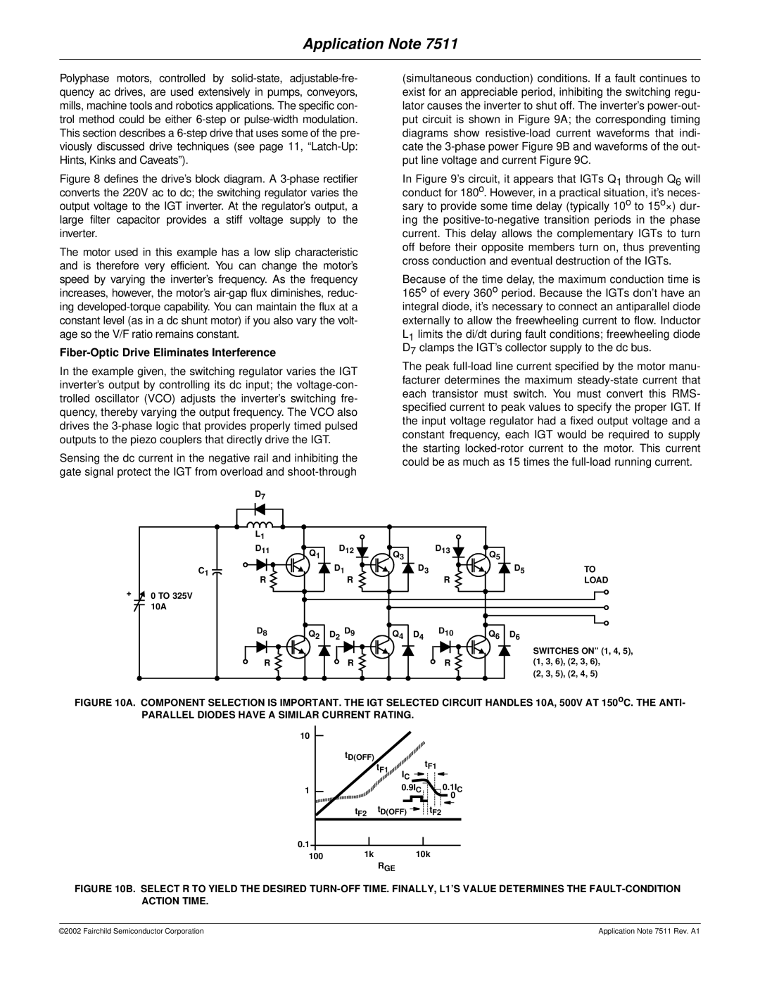
(simultaneous conduction) conditions. If a fault continues to exist for an appreciable period, inhibiting the switching regu- lator causes the inverter to shut off. The inverter’s power-out- put circuit is shown in Figure 9A; the corresponding timing diagrams show resistive-load current waveforms that indi- cate the 3-phase power Figure 9B and waveforms of the out- put line voltage and current Figure 9C.

In Figure 9’s circuit, it appears that IGTs Q1 through Q6 will conduct for 180o. However, in a practical situation, it’s neces- sary to provide some time delay (typically 10o to 15o×) dur- ing the positive-to-negative transition periods in the phase current. This delay allows the complementary IGTs to turn off before their opposite members turn on, thus preventing cross conduction and eventual destruction of the IGTs.

Because of the time delay, the maximum conduction time is 165o of every 360o period. Because the IGTs don’t have an integral diode, it’s necessary to connect an antiparallel diode externally to allow the freewheeling current to flow. Inductor L1 limits the di/dt during fault conditions; freewheeling diode D7 clamps the IGT’s collector supply to the dc bus.

The peak full-load line current specified by the motor manu- facturer determines the maximum steady-state current that each transistor must switch. You must convert this RMS- specified current to peak values to specify the proper IGT. If the input voltage regulator had a fixed output voltage and a constant frequency, each IGT would be required to supply the starting locked-rotor current to the motor. This current could be as much as 15 times the full-load running current.

D7


L1


D11

Q1

D12

Q3


D13

Q5


C1


D1


D3

R


D5

TO

R


R


LOAD

0 TO 325V


10A


D8

Q2

D2 D9

Q4

D4

D10

Q6

D6


SWITCHES ON” (1, 4, 5),

R


R


R


(1, 3, 6), (2, 3, 6),


(2, 3, 5), (2, 4, 5)

FIGURE 10A. COMPONENT SELECTION IS IMPORTANT. THE IGT SELECTED CIRCUIT HANDLES 10A, 500V AT 150oC. THE ANTI-

PARALLEL DIODES HAVE A SIMILAR CURRENT RATING.

10


tD(OFF)


tF1


tF1

IC


1


0.9I


0.1I


C

0 C

t

F2

tD(OFF)

tF2


0.1

1k


10k


100


RGE

FIGURE 10B. SELECT R TO YIELD THE DESIRED TURN-OFF TIME. FINALLY, L1’S VALUE DETERMINES THE FAULT-CONDITION ACTION TIME.

©2002 Fairchild Semiconductor Corporation

Application Note 7511 Rev. A1

Page 6
Image 6
Fairchild AN-7511 manual Fiber-Optic Drive Eliminates Interference

AN-7511 specifications

The Fairchild AN-7511 is a versatile, twin-engine turboprop aircraft designed for a myriad of military applications, including cargo transport, surveillance, and personnel movement. Developed by Fairchild Aircraft in the 1970s, the AN-7511 represents a significant evolution in tactical airlift capabilities, aimed at meeting the diverse needs of the United States Armed Forces and allied nations.

One of the standout features of the AN-7511 is its impressive cargo capacity. The aircraft can carry up to 10 tons of cargo, making it suitable for transporting supplies, equipment, and even troops in various operational scenarios. Its rear ramp design facilitates rapid loading and unloading, which is crucial in military operations where time can be of the essence.

The AN-7511 is powered by two turboprop engines, which provide a combination of efficiency and reliability. These engines offer superior performance at various altitudes and are designed to operate in diverse environmental conditions. The aircraft’s range allows it to execute long-distance missions without the need for frequent refueling, which is vital for sustained operations in remote areas.

In terms of technologies, the AN-7511 features advanced avionics that enhance navigation and situational awareness for the crew. These systems incorporate modern instruments that ensure safe flight operations, even in challenging weather conditions. The cockpit layout is designed for ease of use, enabling pilots to maintain focus on mission objectives.

Another notable characteristic of the AN-7511 is its rugged construction. The airframe is built to endure the rigors of military flights, including rough landings on unpaved airstrips. This durability is complemented by a relatively short takeoff and landing distance, allowing the aircraft to operate in austere environments.

Moreover, the AN-7511 can be equipped with various mission-specific systems, such as surveillance pods or electronic warfare equipment, making it adaptable for different roles. This flexibility extends the operational capabilities of the aircraft, enabling it to fulfill multiple mission types in support of military objectives.

In summary, the Fairchild AN-7511 is a robust and adaptable aircraft that combines advanced technologies with military practicality. Its cargo capacity, range, reliability, and operational flexibility make it a valuable asset for any airlift or tactical operation, ensuring that it remains a critical component of military aviation efforts.