PRELIMINARY
3.2.3 TTL Trigger Source
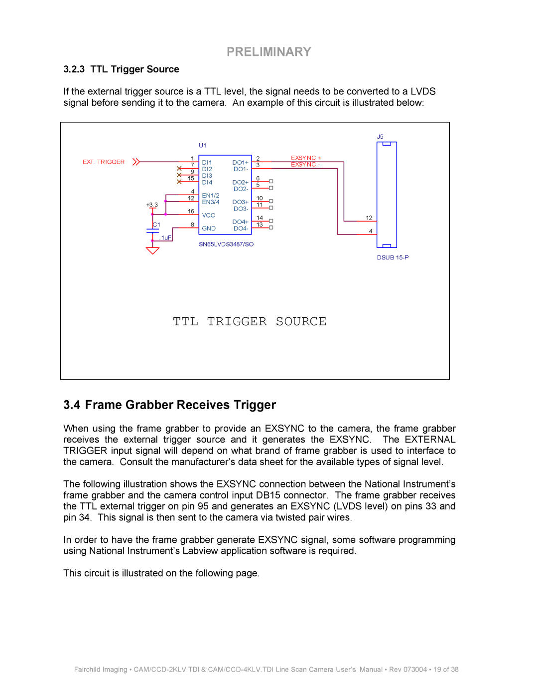
If the external trigger source is a TTL level, the signal needs to be converted to a LVDS signal before sending it to the camera. An example of this circuit is illustrated below:
|
|
|
|
|
|
|
|
|
| U1 |
|
|
|
|
|
|
|
|
EXT. TRIGGER |
|
|
|
|
|
|
|
| 1 |
|
|
| 2 |
|
| EXSYNC + |
|
|
|
|
|
|
|
|
| DI1 | DO1+ |
|
|
| |||||||
|
|
|
|
|
|
| 7 |
| 3 |
|
| EXSYNC - |
|
| ||||
|
|
|
|
|
|
|
| DI2 | DO1- |
|
|
|
|
| ||||
|
|
|
|
|
|
|
|
| 9 |
|
|
|
|
|
|
| ||
|
|
|
|
|
|
|
| DI3 |
|
|
|
|
|
|
|
| ||
|
|
|
|
|
|
|
| 15 |
|
| 6 |
|
|
|
|
| ||
|
|
|
|
|
|
|
| DI4 | DO2+ |
|
|
|
|
|
| |||
|
|
|
|
|
|
|
|
|
|
| 5 |
|
|
|
|
| ||
|
|
|
|
|
|
|
|
|
|
|
|
|
|
|
| |||
|
|
|
|
|
|
|
|
| 4 | EN1/2 | DO2- |
|
|
|
|
|
| |
|
|
|
|
|
|
|
|
|
|
|
|
|
|
| ||||
|
|
|
|
|
|
|
|
|
|
|
|
|
|
|
| |||
|
|
|
|
|
|
|
| 12 |
|
| 10 |
|
|
|
|
| ||
|
|
|
|
|
|
|
| EN3/4 | DO3+ |
|
|
|
|
|
| |||
+3.3 |
|
|
|
|
| 11 |
|
|
|
|
| |||||||
|
|
|
|
|
|
|
|
|
| |||||||||
|
| 16 | VCC | DO3- |
|
|
|
|
|
| ||||||||
|
|
|
|
|
|
|
|
| 14 |
|
|
|
|
| ||||
|
|
|
|
|
|
|
|
|
| DO4+ |
|
|
|
|
|
| ||
|
|
|
|
|
|
|
|
|
|
|
|
|
|
|
|
|
| |
|
|
|
| C1 | 8 | GND | DO4- |
| 13 |
|
|
|
|
| ||||
|
|
|
|
|
| .1uF |
|
|
|
|
|
|
|
|
| |||
|
|
|
|
|
|
|
|
|
|
|
|
|
|
|
|
| ||
|
|
|
|
|
| SN65LVDS3487/SO |
|
|
|
|
|
| ||||||
|
|
|
|
|
|
|
|
|
|
|
|
|
|
|
| |||
J5
12
4
DSUB
TTL TRIGGER SOURCE
3.4 Frame Grabber Receives Trigger
When using the frame grabber to provide an EXSYNC to the camera, the frame grabber receives the external trigger source and it generates the EXSYNC. The EXTERNAL TRIGGER input signal will depend on what brand of frame grabber is used to interface to the camera. Consult the manufacturer’s data sheet for the available types of signal level.
The following illustration shows the EXSYNC connection between the National Instrument’s frame grabber and the camera control input DB15 connector. The frame grabber receives the TTL external trigger on pin 95 and generates an EXSYNC (LVDS level) on pins 33 and pin 34. This signal is then sent to the camera via twisted pair wires.
In order to have the frame grabber generate EXSYNC signal, some software programming using National Instrument’s Labview application software is required.
This circuit is illustrated on the following page.
Fairchild Imaging •