Electrical Characteristics | TA = 25°C unless otherwise noted |
|
|
|
| |||
Symbol | Parameter |
| Test Conditions | Min | Typ | Max | Units | |
|
|
|
|
|
|
|
| |
|
|
|
|
| ||||
IS | Maximum Continuous |
|
| 2.3 | A | |||
VSD | VGS = 0 V, | IS = 2.3 A (Note 2) |
| 0.76 | 1.2 | V | ||
trr | Diode Reverse Recovery Time |
| IF = 12 A, | diF/dt = 100 A/µs |
| 24 |
| nS |
Qrr | Diode Reverse Recovery Charge |
|
|
|
| 13 |
| nC |
|
|
|
|
|
|
|
|
|
Notes:
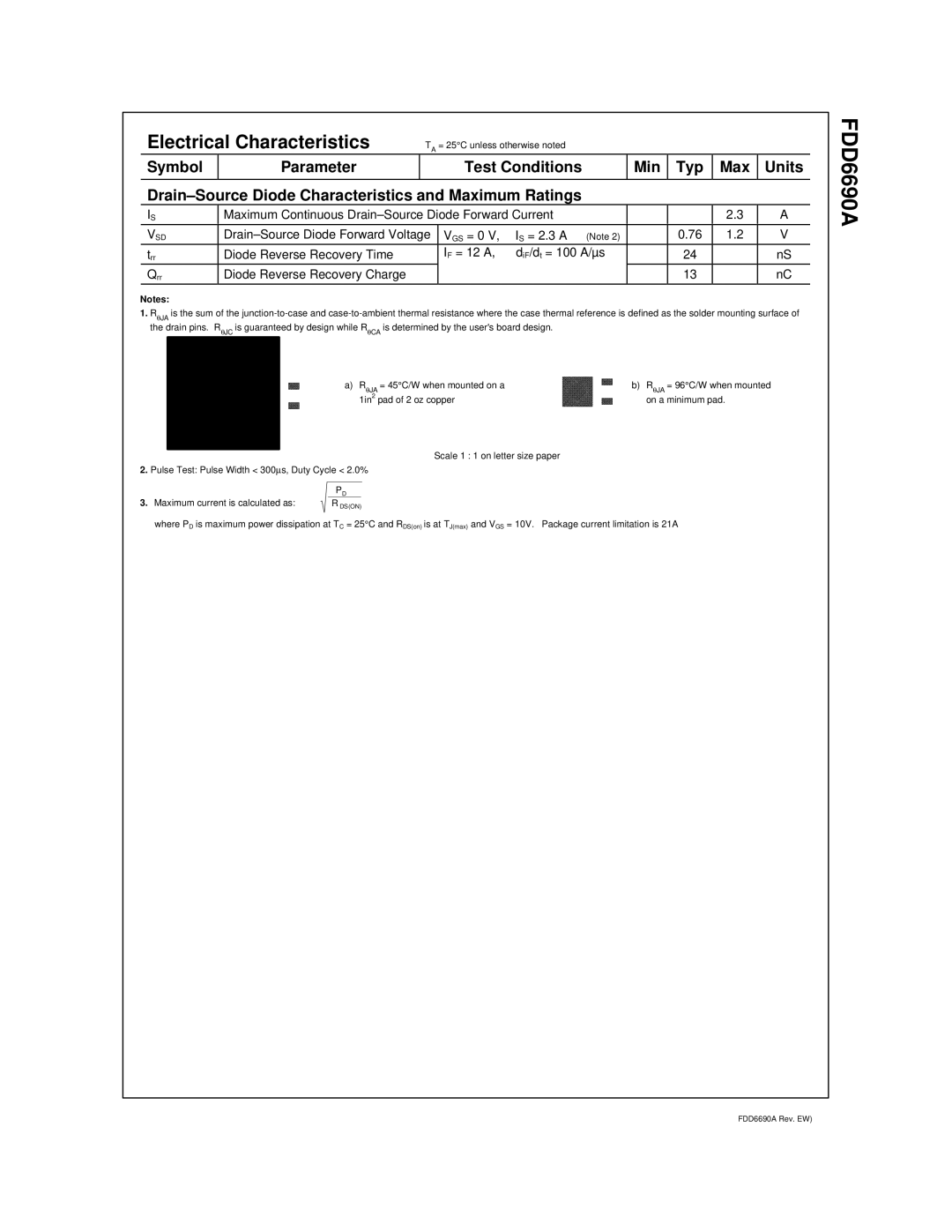
1.RθJA is the sum of the
a) RθJA = 45°C/W when mounted on a | b) RθJA = 96°C/W when mounted |
1in2 pad of 2 oz copper | on a minimum pad. |
Scale 1 : 1 on letter size paper
2.Pulse Test: Pulse Width < 300μs, Duty Cycle < 2.0%
PD
3. Maximum current is calculated as: | R DS(ON) |
where PD is maximum power dissipation at TC = 25°C and RDS(on) is at TJ(max) and VGS = 10V. Package current limitation is 21A
FDD6690A
FDD6690A Rev. EW)