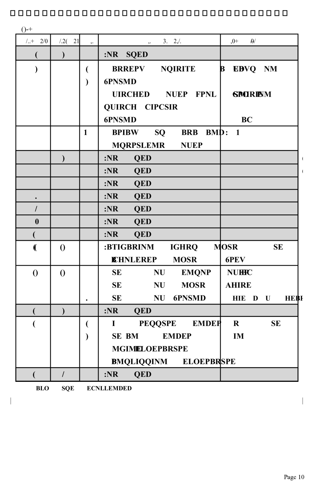
Appendix 1. Installation and Wiring
Table1
Connector | Contacts | Pin | Pin Function | Wire Color |
P1 | 2 |
| Not used |
|
P2 | 4 | 1 | Battery Positive (always on)* | Red |
|
| 2 | Ground |
|
|
| 3 | Switched Power from Ignition | Purple |
|
|
| switch circuit |
|
|
| 4 | Ground | Black |
|
|
|
|
|
P3 | 4 | All | Faria® Bus Data and | N/A |
|
|
| Instrument Power |
|
P4 | 2 |
| Not Used | (PJ0015) |
|
|
|
|
|
P5 | 3 |
| Not Used | (PJ0016) |
|
|
|
|
|
P6 | 3 |
| Not Used |
|
|
|
|
|
|
P7 | 3 |
| Not Used |
|
|
|
|
|
|
P8 | PP |
| Not Used |
|
|
|
|
|
|
P9 | PP |
| Not Used |
|
|
|
|
|
|
P10 | PP |
| Not Used |
|
|
|
|
|
|
P11 | 12 | 3 | Navigation Lights Input | Dk. Blue |
|
| 4 | Tachometer Input | Grey |
|
|
|
|
|
P12 | 12 | 5 | Fuel Flow Sensor Power | Black |
|
| 6 | Fuel Flow Input | White |
|
| 7 | Fuel Flow Ground | Shield w/ heat shrink |
|
|
|
|
|
P13 | 2 |
| Not Used |
|
|
|
|
|
|
P14 | 6 | 1 | Oil Pressure Sender | Lt. Blue |
|
| 2 | Fuel Tank Sender | Pink |
|
| 5 | Engine Temperature |
|
|
| 6 | Transmission Temperature |
|
|
|
|
|
|
P15 | 8 |
| Not Used |
|
|
|
|
|
|
*5 amp Fuse Recommended
Page 10
