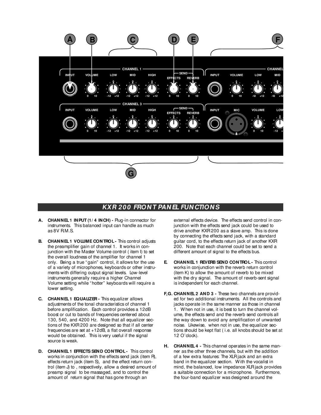
A B C D EF
|
|
| CHANNEL 1 |
|
|
|
|
|
| CHANNEL | |
INPUT | VOLUME | LOW | MID | HIGH | SEND | INPUT | VOLUME | LOW | MID | ||
EFFECTS | REVERB | ||||||||||
|
|
|
|
|
|
|
|
| |||
| 5 |
| 0 |
| 0 |
| 0 |
| 5 |
| 5 |
| 5 |
| 0 |
| 0 |
0 | 10 | +12 | +12 | +12 | 0 | 10 | 0 | 10 | 0 | 10 | +12 | +12 |
INPUT VOLUME
| 5 |
0 | 10 |
CHANNEL 3
LOW MID HIGH
| 0 |
| 0 |
| 0 |
+12 | +12 | +12 |
![]() SEND
SEND![]()
EFFECTS REVERB
| 5 |
| 5 |
0 | 10 | 0 | 10 |
INPUT |
|
|
| MIC | VOLUME | LOW |
| 5 |
| 0 |
0 | 10 | +1 |
G
KXR 200 FRONT PANEL FUNCTIONS
A.CHANNEL 1 INPUT (1/4 INCH) -
B.CHANNEL 1 VOLUME CONTROL - This control adjusts the preamplifier gain of channel 1. It works in con- junction with the Master Volume control ( item I) to set the overall loudness of the amplifier for channel 1 only. Being a true “gain” control, it allows for the use of a variety of microphones, keyboards or other instru- ments with differing output signal levels.
C.CHANNEL 1 EQUALIZER - This equalizer allows adjustments of the tonal characteristics of channel 1 before amplification. Each control provides a 12dB boost or cut to bands of frequencies centered about 130, 540, and 4200 Hz. Note that all equalizer sec- tions of the KXR 200 are designed so that if all center frequencies are set at +12dB, a flat overall response would be obtained. This is very useful if the signal source is weak.
D.CHANNEL 1 EFFECTS SEND CONTROL - This control works in conjunction with the effects send jack (item R), effects return jack (item S), and the effect return con- trol (item J) to , respectively, allow a desired amount of preamp signal to be massaged, and to control the amount of return signal that has gone through an
external effects device. The effects send control in con- junction with the effects send jack could be used to drive another KXR 200 as a slave amp. This is done by connecting the effects send jack, with a standard guitar cord, to the effects return jack of another KXR
200. Note that each channel could be set to send a different amount of signal to the effects bus.
E.CHANNEL 1 REVERB SEND CONTROL - This control works in conjunction with the reverb return control (item K) to allow the amount of reverb to be mixed with the dry signal. The amount of
F,G. CHANNEL 2 AND 3 - These two channels are provid- ed for two additional instruments. All the controls and jacks operate in the same manner as those in channel
1.When not in use, it is best to turn the channel vol- ume, the effects send and the reverb send controls all the way down to avoid any amplification of unwanted noise. Likewise, when not in use, the equalizer sec- tions should be kept flat ( i.e. all knobs should be set at
12O’clock).
H.CHANNEL 4 - This channel operates in the same man- ner as the other three channels, but with the addition of a few extra features: The XLR jack and an extra band in the equalizer section. With the vocalist in mind, the balanced, low impedance XLR jack provides a suitable connection for a microphone. Furthermore, the