FI J K L M
| CHANNEL 2 |
|
|
| MASTER |
|
|
| ON | ||
LOW | MID | HIGH | SEND | VOLUME | RETURN |
|
|
|
|
|
|
|
|
|
|
|
| ||||||
|
|
|
|
|
| ||||||
|
|
|
|
|
|
|
| ||||
|
|
|
|
|
| EFFECTS | REVERB |
|
| EFFECTS | REVERB | ||||
| 0 |
| 0 |
| 0 |
| 5 |
| 5 |
| 5 |
| 5 |
| 5 |
|
|
|
|
|
|
|
|
|
|
|
|
|
|
| ON |
+12 | +12 | +12 | 0 | 10 | 0 | 10 | 0 | 10 | 0 | 10 | 0 | OFF | |||
10 | |||||||||||||||
DELTACOMPTM
CHANNEL 4
VOLUME | LOW | LOW MID |
| 5 |
| 0 |
| 0 |
0 | 10 | +12 | +12 |
HIGH MID | HIGH |
| 0 |
| 0 |
+12 | +12 |
![]() SEND
SEND![]()
EFFECTS | REVERB | ||
| 5 |
| 5 |
0 | 10 | 0 | 10 |
POWER
KEYBOARD
EXTENDED
RANGE
Two hundred
H | N | O |
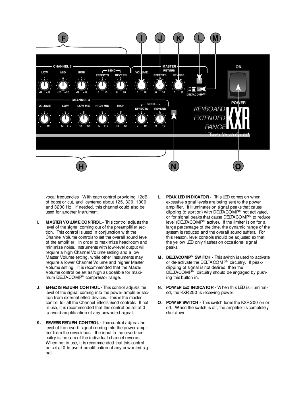
vocal frequencies. With each control providing 12dB of boost or cut, and centered about 125, 320, 1000 and 3200 Hz. If needed, this channel could also be used for another instrument.
I.MASTER VOLUME CONTROL - This control adjusts the level of the signal coming out of the preamplifier sec- tion. This control is used in conjunction with the Channel Volume controls to set the overall sound level of the amplifier. In order to maximize headroom and minimize noise, instruments with
J.EFFECTS RETURN CONTROL - This control adjusts the level of the signal coming into the power amplifier sec- tion from external effect devices. This is the master control for all the Channel Effects Send controls. If not in use, it is recommended that this control be set at 0 to avoid amplification of any unwanted signal.
K.REVERB RETURN CONTROL - This control adjusts the level of the reverb signal coming into the power ampli- fier from the reverb bus. The input to the reverb cir- cuitry is the sum of the individual channel reverbs. When not in use, it is recommended that this control be set at 0 to avoid amplification of any unwanted sig- nal.
L.PEAK LED INDICATOR - This LED comes on when excessive signal levels are being sent to the power amplifier. It illuminates on signal peaks that cause clipping (distortion) with DELTACOMPTM not activated, or for signal peaks that cause DELTACOMPTM to reduce level (DELTACOMPTM active). If the limiter is on for a large percentage of the time, the dynamic range of the system is reduced and the overall sound suffers. For this reason, level controls should be adjusted so that the yellow LED only flashes on occasional signal peaks.
M.DELTACOMPTM SWITCH - This switch is used to activate or
N.POWER LED INDICATOR - When this LED is illuminat- ed, the KXR 200 is receiving power.
O.POWER SWITCH - This switch turns the KXR 200 on or off. When the switch is off, the amplifier is completely shut down.