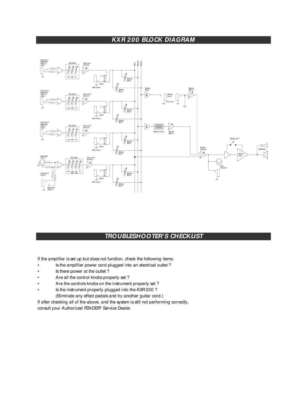
KXR 200 BLOCK DIAGRAM
Channel 1
Balanced
High Z
Input
Channel 2
Balanced
High Z
Input
Channel 3
Balanced
High Z
Input
Equalizer | Channel 1 | |
|
| Volume |
Low Mid | Hi |
|
|
| Insert |
|
| (Rear Panel) |
Equalizer | Channel 2 | |
|
| Volume |
Low Mid | Hi |
|
|
| Insert |
|
| (Rear Panel) |
Equalizer | Channel 3 | |
|
| Volume |
Low Mid | Hi |
|
|
| Insert |
Main | Reverb | Effects |
|
Reverb |
|
|
|
Send |
|
|
|
Effects |
| Effects | Effects |
| Send | Return | |
Send |
|
|
|
|
|
| Effects |
|
|
| Loop |
|
|
| (Rear Panel) |
Reverb |
|
|
|
Send |
|
|
|
Effects |
|
|
|
Send |
|
|
|
|
| Reverb Circuit | Reverb |
|
|
| Return |
Reverb |
|
|
|
Send |
|
|
|
|
|
| Master |
|
|
| Volume |
DeltacompTM
Speakers
Balanced Low Z
Channel 4 Inputs
Equalizer |
| |
Low Low | Hi | Hi |
Mid | Mid |
|
(Rear Panel)
Channel 4
Volume
Insert
Effects |
Send |
Reverb |
Send |
Power
Amp
Line
Outputs
Balanced High Z
(Rear Panel)
Effects |
Send |
TROUBLESHOOTER‘S CHECKLIST
If the amplifier is set up but does not function, check the following items:
•Is the amplifier power cord plugged into an electrical outlet ?
•Is there power at the outlet ?
•Are all the control knobs properly set ?
•Are the controls knobs on the instrument properly set ?
•Is the instrument properly plugged into the KXR 200 ? (Eliminate any effect pedals and try another guitar cord.)
If after checking all of the above, and the system is still not performing correctly, consult your Authorized FENDER® Service Dealer.
