EEI J I J
|
|
|
| A PRODUCT OF: |
|
|
|
|
|
|
|
| |
|
|
|
|
|
|
|
|
|
|
|
| ||
|
|
|
|
|
|
|
|
|
|
|
| ||
|
|
|
| FENDER MUSICAL |
|
|
|
|
|
|
| SERIAL | |
TYPE: PR200 |
| INSTRUMENTS CORP., |
|
|
|
|
|
| |||||
| CORONA, CA 91720 |
|
| 600 WATTS |
|
| |||||||
CAUTION: CHASSIS SURFACE HOT |
|
|
|
| 8 OHM MINIMUM |
|
| ||||||
WARNING: TO REDUCE THE RISK OF FIRE OR |
|
|
|
| LOAD BRIDGED |
|
| ||||||
ELECTRIC SHOCK, DO NOT EXPOSE THIS EQUIPMENT |
|
|
|
|
| 300 WATTS |
|
|
| 300 WATTS |
|
| |
TO RAIN OR MOISTURE |
|
|
|
|
|
|
|
|
| ||||
|
|
|
|
|
| 4 OHM MINIMUM |
|
| 4 OHM MINIMUM |
|
| ||
|
|
|
|
|
|
|
|
|
|
|
|
|
|
ATTENTION: | CAUTION: |
UTILISER UN | TO REDUCE |
FUSIBLE DE | THE RISK OF |
RECHANGE | FIRE, REPLACE |
DE MEME | FUSE WITH |
=(+)TIP
=
![]() MONO
MONO
![]() BRIDGE
BRIDGE
1/4"
PHONE
DUAL
MONO
FOR MONO BRIDGE
OPERTION, USE
L MFFK GH K
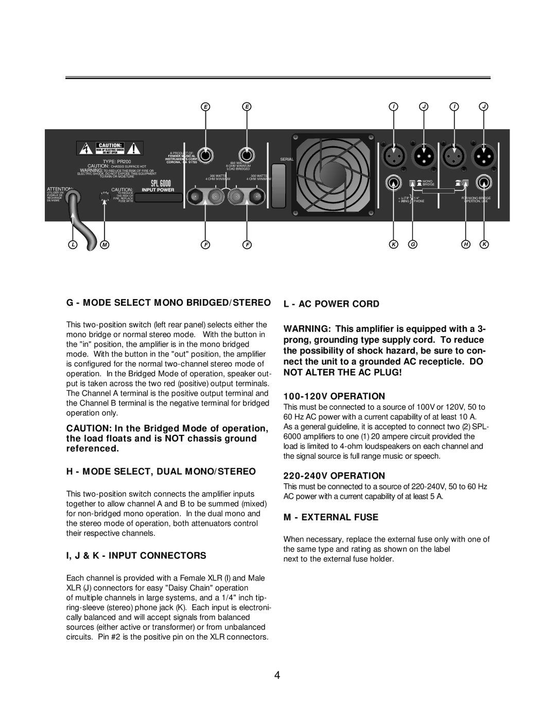
G - MODE SELECT MONO BRIDGED/STEREO
This
CAUTION: In the Bridged Mode of operation, the load floats and is NOT chassis ground referenced.
H - MODE SELECT, DUAL MONO/STEREO
This
I, J & K - INPUT CONNECTORS
Each channel is provided with a Female XLR (I) and Male XLR (J) connectors for easy "Daisy Chain" operation
of multiple channels in large systems, and a 1/4" inch tip-
L - AC POWER CORD
WARNING: This amplifier is equipped with a 3- prong, grounding type supply cord. To reduce the possibility of shock hazard, be sure to con- nect the unit to a grounded AC recepticle. DO NOT ALTER THE AC PLUG!
100-120V OPERATION
This must be connected to a source of 100V or 120V, 50 to 60 Hz AC power with a current capability of at least 10 A. As a general guideline, it is accepted to connect two (2) SPL- 6000 amplifiers to one (1) 20 ampere circuit provided the load is limited to
220-240V OPERATION
This must be connected to a source of
M - EXTERNAL FUSE
When necessary, replace the external fuse only with one of the same type and rating as shown on the label
next to the external fuse holder.
4